Basic Knowledge of Thermal Management (3)
-Thermal Design and Management-
2019-03-18
Introduction
Thermal management is an important process to ensure the characteristics, life, and safety of equipment and systems. "Basic Knowledge of Thermal Management" explains the basics for implementing the necessary thermal management in three parts, namely "Basic Knowledge of Heat," "Background of the Need for Thermal Management," and "Thermal Design and Management." This issue is the third and final part, i.e. "Thermal Design and Management."
What is Thermal Design?
Thermal design refers to incorporating the necessary thermal management through thermal simulations, etc., during the product design phase.
Components in older electrical products were arranged with adequate space, and it was therefore sufficient to verify the need for thermal management in the final phase of product development. However, in recent years, it has become important to incorporate thermal management into the design during the design phase due to the downsizing and high performance of equipment.
For example, if the need for thermal management in equipment with predetermined dimensions is identified in the final evaluation phase, suddenly requiring fans, then the entire circuit design will need to be reexamined to secure space for installing fans. The product plan itself can be abandoned in some cases.
However, identifying the equipment temperature distribution through thermal simulations and implementing thermal management during the design phase enables efficient product development.
Thermal Design Processes
Roughly speaking, thermal design consists of four processes, i.e., specifying upper limit temperature conditions, investigating the heat generation and thermal conductivity characteristics of parts/materials , implementing thermal simulations, and examining thermal management. If the simulation results exceed the specified temperatures, then simulations will be conducted again after appropriate thermal management is examined and incorporated. This will be repeated until the temperatures fall to the specified values or lower.
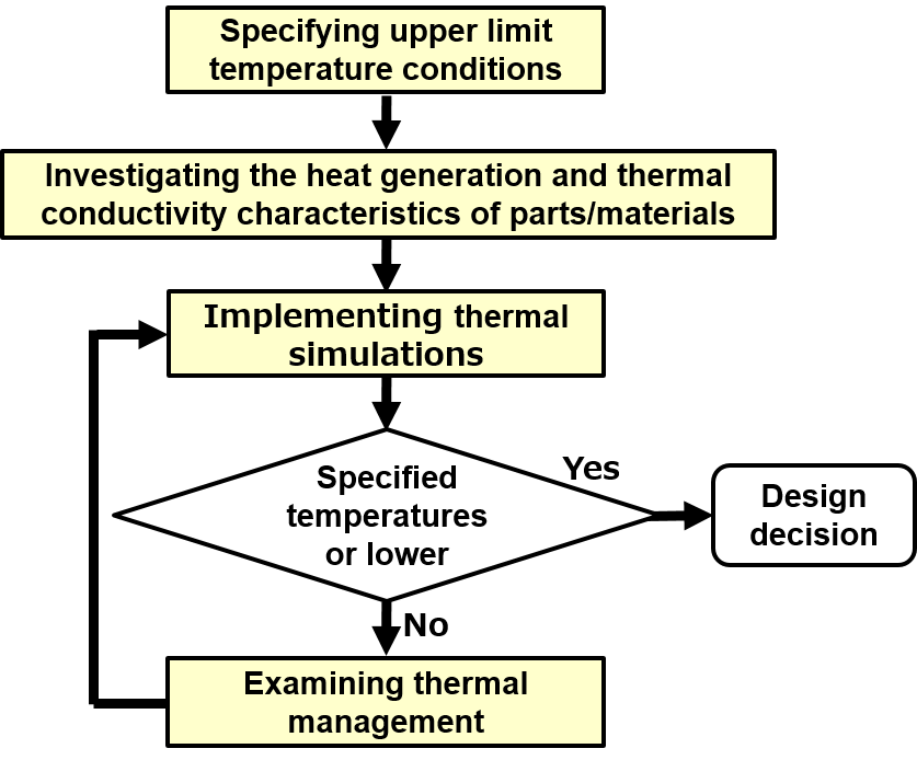
It should be noted that thermal simulations are not very accurate, and it is sometimes difficult to incorporate management details into simulations. Therefore, it is ultimately necessary to determine management methods through temperature measurements using actual equipment. Nevertheless, implementing thermal design can significantly lower the risk of circuit design reexamination in the final evaluation phase compared to cases when it is not implemented. Each process is explained below.
Specifying upper limit temperature conditions
Specifying the upper limit equipment ambient temperature
Because the internal temperature of equipment is significantly affected by its ambient temperature, it is recommended to specify low upper limits for equipment operating temperatures in terms of the cooling of equipment interior. However, from the perspective of users, it is preferable that the temperature specifications not be restricted by the operating environment.
Therefore, the operating temperature range that has taken both perspectives into consideration should be specified in advance as part of the product specifications.
Specifying the upper limit equipment internal temperature
The maximum operating temperature of each is investigated, and the upper limit is specified so that the components will not exceed their maximum operating temperature.
It should be noted that for components whose life has a strong correlation with temperature, such as aluminum electrolytic capacitors, it is sometimes necessary to specify temperatures lower than the maximum operating temperatures of components by taking their life into consideration.
Specifying equipment surface temperature
For equipment that may cause burns when reaching a high temperature, such as mobile equipment, it is necessary to specify a surface temperature for its case.
Investigating the Heat Generation and Thermal Conductivity Characteristics of Parts/Materials
It is necessary to check to what extent each component generates heat under the equipment's operating conditions.
Electronic components generate heat due to energy losses when they operate, causing the equipment temperature to rise. In particular, CPUs and power semiconductors require the most careful attention because they generate a large amount of heat.
Various thermal conductivity characteristics (thermal resistance, heat radiation, etc.) also need to be investigated, including parts/materials such as substrates and cases. Since it is often difficult to identify these thermal conductivity characteristics, the creation and use of databases will save time and effort, rather than investigating these characteristics each time.
Implementing Thermal Simulations
Thermal simulations simulate the temperatures of each section depending on component placement and wind flow, with the prerequisites of temperature conditions and thermal characteristics described above.
Although Excel-based calculation is possible, it is easier to conduct an analysis using dedicated thermal fluid analysis software, which is widely available.
Examining Thermal Management
- Reexamining component placement
- Reexamining case materials
- Installing air holes and cooling fans
- Installing heatsinks
- Installing heat pipes
- Installing thermal insulation sheets (between heat-generating components and low heat-resistance components)
- Adopting TIMs (thermal interface materials) (between heat-generating components and heatsinks)
Thermal simulations are conducted again after thermal management is carried out in order to calculate the temperature changes of each section.
Thermal Management Methods
Each of the thermal management items listed in the previous section will be explained in a bit more detail here.
Reexamining Component Placement
Because heat-generating components have a significant thermal impact on other components when placed on the windward side, they should be installed on the leeward side if possible.
It is also effective to keep heat-susceptible components away from heat-generating components, create air passages with cooling taken into consideration, etc.
Reexamining Case Materials
Heat inside equipment is also dissipated to the outside via its case.
The amount of heat dissipation differs significantly depending on the thermal resistance of case materials. For example, plastic cases, which have a high thermal resistance, dissipate small amounts of heat, whereas aluminum cases, which have a low thermal resistance, dissipate large amounts of heat.
Changing case materials to those with a low thermal resistance will increase cooling effects.
In addition, cases have large surface areas and can therefore be used as substitutes for heatsinks. It is also effective to dissipate heat by placing heat-generating components in close contact with cases.
Installing Air Holes and Cooling Fans
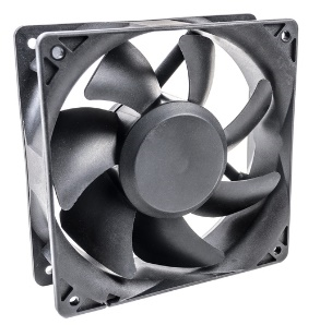
Although providing air holes in the upper section of a case can achieve cooling effects to a certain extent, using cooling fans in addition to the air holes will achieve much greater effects. In this case, the installation location of a cooling fan should be determined with consideration given to air passages that achieve high cooling effects inside the case.
It should be noted that cooling fans cannot be used when there are unacceptable installation issues related to securing space and increases in noise and power consumption.
Installing Heatsinks
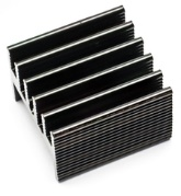
Heatsinks, also called radiators, are components attached to heating elements with the aim of absorbing and dissipating heat. Heatsinks are often made of materials that have high conductivity performance, such as aluminum, iron, and copper, and usually have a number of fins to increase the heat transfer area. Although heatsinks are effective components for increasing the heat dissipation area, they have a relatively large weight and size (volume) and therefore require adequate space for their use.
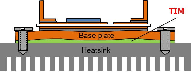
It should be noted that thermal interface materials (TIMs) for increasing thermal conductivity are usually used for joining heating elements and heatsinks.
Installing Heat Pipes
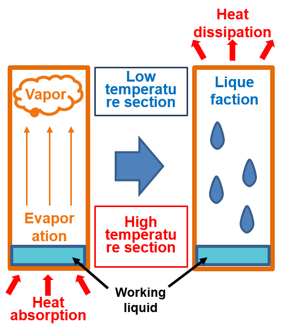
Heat pipes consist of special sealed pipes containing a highly volatile liquid. They are used to diffuse heat and feature high heat diffusion effects. The diagram on the right shows the principle of heat diffusion by heat pipe. The working liquid inside a heat pipe absorbs the heat of the high temperature section and evaporates. The vapor moves to the low temperature section, dissipates heat, and liquefies. The liquefied working liquid then refluxes. This cycle is repeated to diffuse heat.
Typical applications examples include CPU coolers.
Installing Thermal Insulation Sheets
Although heat-susceptible components must be kept away from heat-generating components, when it is difficult due to circuit design, it is effective to install thermal insulation sheets between them to protect heat-susceptible components.
Installing thermal insulation sheets between cases and heat-generating components is also effective when the case surface temperatures of mobile equipment, etc., need to be suppressed.
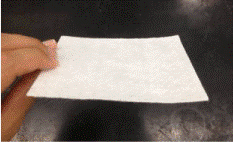
Adopting TIMs (Thermal Interface Materials)
When cooling heat-generating components using heatsinks, if there are gaps at their joint surfaces, then efficient cooling cannot be achieved due to high contact thermal resistance. In such cases, filling the gaps on the joint surface of heat-generating components and heatsinks with a TIM with low thermal resistance will increase the cooling effects.
Typical TIMs are introduced below.
Thermal greases
Thermal greases are TIM materials that are applied between heating elements and heatsinks. They have been around a long time and are the most common and cheapest TIMs. However, it is difficult to apply them uniformly, and there is also an issue of long-term reliability.
Thermal conductivity sheets
Thermal conductivity sheets, which are sheet-like with excellent thermal conductivity, are a TIM material that is used sandwiched between heating elements and heatsinks. They include silicon, elastomer, and graphite sheets, and can substitute for thermal greases. They are easy to handle but require pressure to achieve adequate contact.
PCM (phase change material)
PCMs, which are low thermal resistant materials that soften at high temperatures, are TIM materials used sandwiched between heating elements and heatsinks. They feature reduced contact thermal resistance due to improved adhesion caused by softening at high temperatures. Although they are sheet-like and easy to handle, there are cost issues.
Summary
Thermal design refers to incorporating thermal management through thermal simulations, etc., during the product design phase. This enables efficient design in accordance with the circuit design.
There are suitable approaches for thermal simulations and management, respectively, and a variety of methods and parts/materials are available to achieve them. Implementing thermal management requires the understanding of parts/materials features, comparison and examination of their performance, and use of the right parts/materials in the right places.
Although this is the last issue of "Basic Knowledge of Thermal Management," we are planning to introduce case examples of problem solving using TIMs with excellent performance in a separate issue.


