① High-speed differential data transmission and common mode noise issues
Differential mode is the mainstream of data transmission for today's digital communication interfaces, including USB and HDMI.
One of the approaches to speeding up data transmission is to reduce the amplitude and thereby make the transition time relatively short to increase the transmission rate.
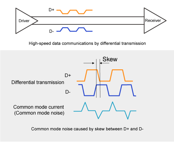
The conventional single-ended transmission is relatively susceptible to the effects of external noise or the ground when the amplitude is reduced. Differential transmission uses a pair of lines to transmit signals of an equal amplitude in reverse phase (D+, D-) and receive the difference.
Therefore, this mode is less affected by external noise or the ground. Also, the magnetic field around the two lines is cancelled, reducing spurious radiation.
For these reasons, the differential transmission mode is used for most applications of high-speed data transmission.
Even differential transmission may generate common mode noise in cases such as superimposed noise from other circuits via capacitive coupling or an imbalance between D+ and D- signals.
Examples of the latter include skew caused by the difference in the conductor length of PCB patterns, the difference in the edge rate between D+ and D- signals, the difference in the pulse width, and mode conversion, i.e., conversion of part of a differential signal into common mode caused when the transmission lines are highly asymmetric.
Under these conditions, common mode noise is generated at the same frequency band as that of the differential signal.
This is why common mode noise cannot be removed by a low pass filter (LPF), which is a frequency separation type filter that has been used in conventional single-ended analog circuits.
Therefore, common mode filters, which can separate data signals (differential mode) from noise (common mode) according to the transmission mode, are now widely used as standard filters for differential transmission.
② What are common mode filters?
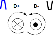
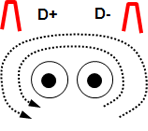
A common mode filter has two magnetically coupled coils, one of which is connected to D+ and the other to D- in differential transmission lines.
How a filter having such a structure works when a differential mode signal and common mode noise enters is described below using a diagram showing a state equivalent to magnetic coupling.
When a differential mode signal enters, the flux generated by the D+ signal and that by the D- signal in the magnetically coupled circuit cancel each other out, generating no impedance and passing the differential mode signal.
When a common mode noise enters, the flux generated by the D+ signal and that by the D- signal enhance each other, generating high impedance and preventing common mode noise from passing.
In other words, common mode filters serve as transmission lines for differential mode signals, and as inductors for common mode noise.
The impedance of the filters serving as inductors for common mode noise is called common mode impedance. Normally, the impedance value at 100 MHz is used as a typical indicator of common mode noise rejection performance.
As in the description above, the structure of magnetic coupling between the coils of the D+ and D- transmission lines is the key factor of the ability to separate differential signals from common mode noise.
| Schematic diagram | Transmission mode | Effect (cross sections of coils) | Equivalent function |
|---|---|---|---|
 Magnetic coupling between D+ and D- |
Differential mode ↓ Digital signal |
 Fluxes: Cancelled out Impedance: Low |
 Transmission line |
| Common mode ↓ Noise component |
 Fluxes: Enhanced Impedance: High |
 Inductor |
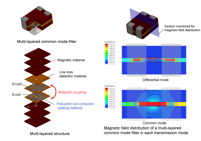
③ Structure and operation of multi-layered common mode filters
The left-hand figure below shows the structure of our actual multi-layered common mode filter.
One of our product features is the fine-pitch coils achieved by forming using a plating method instead of the conventional printing method. The fine coil conductors and magnetic materials enhance the common mode noise rejection performance.
Different materials including a low loss dielectric material are layered around coil conductors. With this structure, the strong magnetic coupling between the two coils and the reduction of parasitic component, such as parasitic capacitance, reduce losses in differential mode, allowing for high-speed data transmission.
The right-hand figures below show the magnetic field distribution in the filter when a differential mode signal is input and that when a common mode noise is input.
As described in the previous section, in differential mode, the magnetic field is generated only between the coils, and the surrounding magnetic field is cancelled out, indicating that the filter is serving as a differential transmission line.
On the other hand, the entire area of the two coils shows a large magnetic field, indicating that the filter is serving as an inductor.