Complete Guide to Interpreting Chip Resistor Resistance Values!
2025-11-25

- Introduction: What Are Chip Resistors?
- Marking Basics: Meanings of Numbers and Symbols
- Special Markings: Zero Ohms and Decimal Point Notation
- Commonly Used Marking Patterns and How to Interpret Them
- Relationships between the E-series Standard and Resistance Values
- Summary
- Related product information
- Related information
1. Introduction: What Are Chip Resistors?
Chip resistors are basic electronic components used to control current in electronic circuits. Designed as surface mounted devices (SMDs) and soldered directly to printed circuit boards (PCBs), they enable compact circuit design. They are widely used in space-constrained electronic devices, such as smartphones, home appliances, and industrial equipment.
The primary functions of chip resistors are current limiting, voltage division, and signal shaping, which are directly linked to circuit stability and safety. Accurately interpreting their resistance values is essential to properly understanding their performance. Selecting an incorrect resistance value can cause a circuit malfunction or failure.
This article explains, in an easy-to-understand manner (even for beginners), how to correctly interpret the resistance values of chip resistors based on the numbers and symbols marked on them.
2. Marking Basics: Meanings of Numbers and Symbols
The surface of a chip resistor usually has a three- or four-digit number marked on it, indicating its resistance value. Unlike color codes for leaded resistors, numeric notation has been adopted to downsize them.
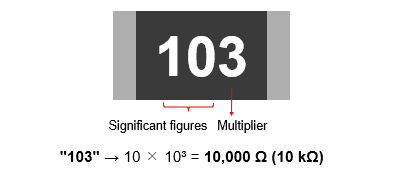
For example, a three-digit number such as "103" means "10 × 10³," corresponding to a resistance value of 10,000 Ω (10 kΩ). The rule of marking is that the first two digits represent the significant figures, and the last digit indicates the multiplier (the power of 10).
A four-digit number such as "1004" means "100 × 10⁴," corresponding to a resistance value of 1,000,000 Ω (1 MΩ). The first three digits represent the significant figures, and the last digit indicates the multiplier.

The unit of resistance is Ω (ohms), with kΩ (kiloohms) and MΩ (megohms) also commonly used.
3. Special Markings: Zero Ohms and Decimal Point Notation
Some chip resistors use special markings that differ from normal ones.
Zero ohm resistor- Markings: "000," "0," etc.
- Meaning: Resistance value ≒ 0 Ω (used as a jumper)
- The letter "R" is used as a substitute for the decimal point.
This notation is particularly common for low resistance values and precision applications. To avoid misinterpretation, it is necessary to check each manufacturer's data sheet.
4. Commonly Used Marking Patterns and How to Interpret Them
Chip resistors have several common markings and corresponding resistance values that are frequently seen in practice. For example, "472" stands for "47 × 10²," corresponding to a resistance value of 4.7 kΩ. "6800" stands for "680 × 10⁰," meaning a resistance value of 680 Ω. These patterns are the standard method to represent resistance values based on the E-series standard (described below) and are frequently used in circuit design. Remembering the rules for interpreting the markings, such as "000" representing zero ohms, "104" representing 100 kΩ, and "222" representing 2.2 kΩ, will make mounted component verification and troubleshooting easier.
| Marking | Resistance value |
How to interpret |
|---|---|---|
| 472 | 4.7kΩ | 47 × 10² |
| 104 | 100kΩ | 10 × 10⁴ |
| 222 | 2.2kΩ | 22 × 10² |
| 6800 | 680Ω | 680 × 10⁰ |
| 000 | 0Ω | Zero ohm resistor |
Due to the low visibility of markings on small components, misinterpreting resistance values can lead to design errors. Learning how to interpret them accurately is essential for highly reliable circuit design.
5. Relationships between the E-series Standard and Resistance Values
Resistor resistance values are designed based on the E-series standard stipulated by IEC 60063 that systematically classifies standard resistor resistance values.
The E-series includes E6, E12, E24, E48, E96, and E192, each with different accuracy and intended uses. For example, the E6 series resistors have an accuracy of ±20% and six resistance values per decade. The E12 resistors have a higher accuracy of ±10%, and the E24 resistors have even a higher accuracy of ±5%, providing more options. The E96 and E192 series are used for high-precision resistors with an accuracy of ±1% or less, making them suitable for measuring instruments and high-reliability circuits.
The E-series resistors play an important role in reducing resistance value variations and standardizing circuit design.
| Series | Accuracy | General application examples |
|---|---|---|
| E6 | ±20% | General applications |
| E12 | ±10% | Home appliances/consumer devices |
| E24 | ±5% | General-purpose electronic circuits |
| E48 | ±2% | Industrial equipment/control circuits |
| E96 | ±1% | High accuracy circuits |
| E192 | ±0.5~0.1% | Measuring instruments/medical equipment |
Understanding the E-series resistors enables you to select suitable resistance values tailored for the required accuracy. Knowing the E-series resistors, along with how to interpret the markings, is the first step to becoming an advanced resistor user.
6. Summary
Accurately interpreting the resistance value of a chip resistor is a fundamental skill in electronic circuit design. A deeper understanding of the marking rules and the E-series standard will improve the accuracy of component selection and help prevent potential problems. Please use this article as a reference and try practicing with actual components to enhance your skills.
7. Related product information
8. Related Information
9. Tags Related to This Article

