Is it essential to a data center? The reasons why a 48V power supply is required and the challenges of power supply design (2)
-Selection of high-performance capacitors-
2021-08-25
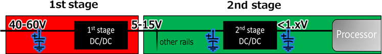
In the last article, we described a 2-stage voltage conversion when applying 48V power in data centers where 48 V is first dropped to intermediate voltage and then converting to the load voltage by the second-stage power supply. (Fig. 1)
This article describes the key points for selecting optimum capacitors for the two-stage method selected as the mainstream system.
Key points to be considered when selecting capacitors
Points of consideration in the 1st stage
The capacitors used in the 48V input section require sufficient capacitance for avoiding instantaneous input power drop and avoiding voltage drop generated by large current load fluctuation in the output side. When capacitance is required, aluminum electrolytic capacitors are generally considered first, but sufficient capacitance reliability needs to be examined according to the application. In a real installation, many operation defect problems were generated in the 2000s caused by some aluminum electrolytic capacitors used in desktop PCs. The problem was identified as a rapid reduction of capacitance caused by the dried-up electrolyte in the long-term high-temperature environment. The solution determined effective was OS-CON using a solid electrolyte. Because OS-CON is strong against capacitance reduction due to solid electrolyte, they contribute to long-term stable operation and high reliability of the final products. (Fig. 2)
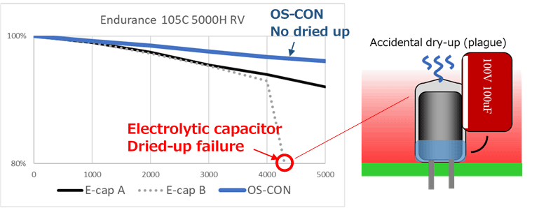
by dried-up electrolyte
Data center equipment including servers require higher reliability than PCs, and an OS-CON has been used for such applications. For the newly adopted 48V lines in data centers, requests for OS-CON using solid-state electrolyte or hybrid capacitors (*1) have been increasing, and 63-100 V rated products are being enhanced by Panasonic.
(*1) Hybrid capacitors ... Hybrid type capacitors use both solid electrolyte and liquid electrolyte for avoiding substantial deterioration caused by drying out as in the case of the electrolytic capacitor using only liquid electrolyte.
Considerations in the 2nd stage
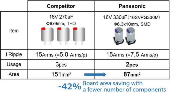
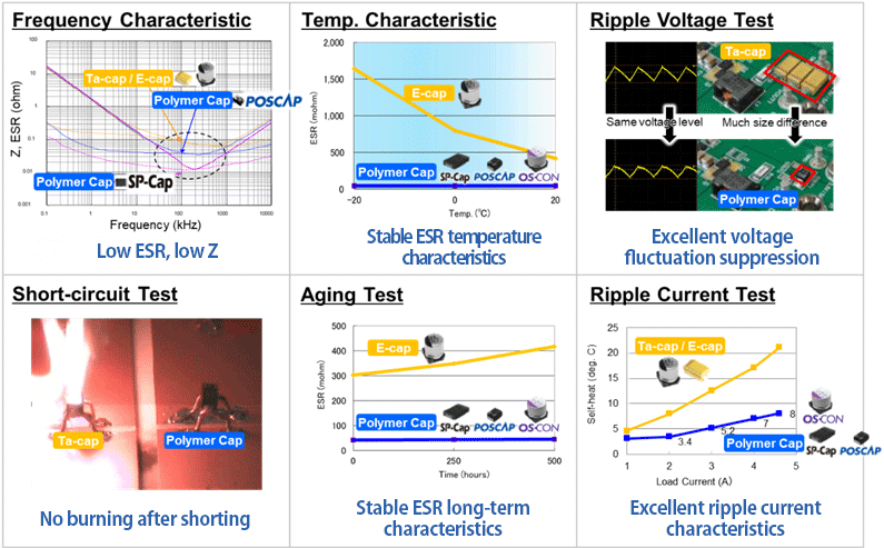
In the 2nd stage power supply design, the component mounting area of each circuit board has been getting tighter. With increasing processor size and number of memory boards for higher performance, as well as adding accelerators along with the 1st stage power supply, board surface area used for the 2nd stage power supply is very limited. In such conditions, Panasonic OS-CON is the best-suited for 2nd stage input bulk capacitors. Compared with electrolytic capacitors, they not only accommodate large current changes with their small size and large capacity, but also stabilize the power supply with a smaller size and a fewer quantity, and have the industry's top-class low ESR and allowable ripple current characteristics. (Fig. 3)
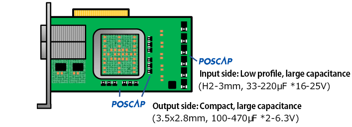
In addition, Panasonic POSCAP provides smaller capacitance than OS-CON as a single component due to the difference in product size, but it is the best-performing capacitor judged on capacitance density by taking advantage of high dielectric constant tantalum. Because of the low-profile product lineup with 1.2 to 2 mm in height, enabling mounting on the bottom surface of a circuit board, the product is used as a solution for providing sufficient capacitance, for example, in servers without sufficient component space on the top surface, compact and thin accelerator/NIC card, and thin profile SSD as a protection capacitor against instantaneous power drop. (Fig. 4)
On the other hand, output side capacitors are increasingly mounted on the bottom surface side of a circuit board due to the densely packed top surface. Because Panasonic SP-Cap achieves large capacity and low ESR even with a low product profile of 2 mm, it is perfectly suited for this industry trend. (Fig. 5)
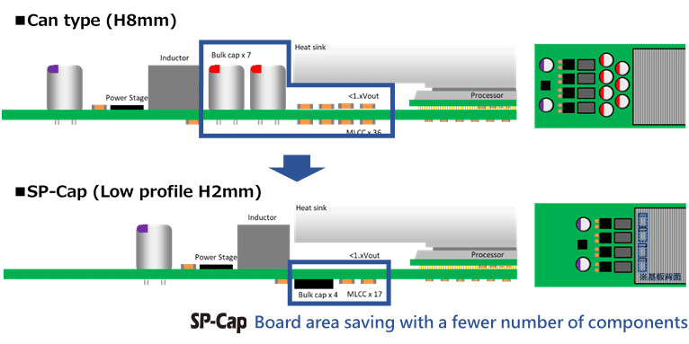
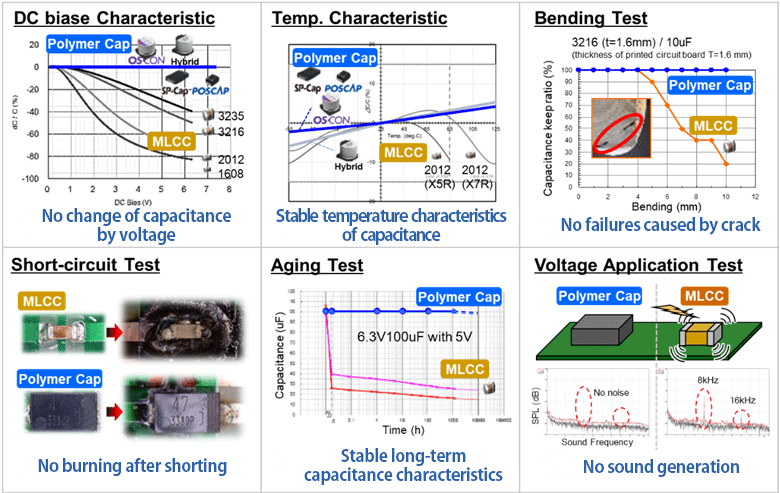
As capacitors mountable on the bottom side of a circuit board, MLCCs are also applied. But the increasing quantity of capacitors as a measure for suppressing current load fluctuation is becoming one of the problems in designs. MLCCs tend to generate a change of characteristics in voltage and temperature, and breakage due to mechanical stress, thereby making the design difficult when the quantity increases. In addition, an increased quantity of MLCCs has often generated problems of cost increase and shortage of supply. SP-Cap provides large capacitance and low ESR characteristics with excellent stability against temperature and voltage by delivering the same capability in a single unit as that of multiple units of MLCC, thereby reducing problems caused by increasing quantity of MLCCs.
As described, by using a well-balanced SP-Cap, a sufficiently stable power supply design becomes possible even with strict circuit area restriction. SP-Cap has the best ESR characteristics among the conductive polymer capacitors and is judged as the best fit in most cases. However, when compact size and large capacitance characteristics are prioritized, then POSCAP will become effective because of its excellent capacitance density as described earlier.
Stability of conductive polymer capacitors
As described in this article, because conductive polymer capacitors are effective for supplementing unstable element characteristics generated in the designs using aluminum electrolytic capacitors and MLCCs, we have received user's comments such as "easy to design," "enabling compact-sizing," "serves for achieving high reliability" in variety of equipment designs.
(Fig. 6, Fig. 7)
In the progress of technological advancement, higher evolution is also required in capacitors. As the major supplier of conductive high-polymer capacitors, Panasonic will continue to make improvements as the principal supplier of conductive polymer capacitors by proposing the optimum product or solution according to each application or use condition of data center equipment and other applications to support power supply designs.
(vs. general-purpose aluminum electrolytic/tantalum capacitors)
An adopted case for use in reference boards
(by Texas Instruments)
As an example in demonstrating the usefulness of Panasonic conductive polymer capacitors in the 48V data center equipment crisis, adoption in the latest power supply reference board is shown here for data centers designed by Texas Instruments, the world top analog IC manufacturer.
Target solution 1 (1st stage)
Solution for data centers
and communication equipment developed
by Texas Instruments
Design number: PMP22510
https://www.ti.com/tool/PMP22510
Space-saving and high-efficiency
(peak 95%) conversion from 48 V
to the intermediate voltage
Specifications:60Vin max (48V typ)
- 1.8-5V 40A max
Controller IC: TPS53667
Adopted Panasonic products
- ① Hybrid capacitors
- Part number: EEHZA1J100P
(63V,10μF,120mΩ,ø10xH10.2mm) - ② Metal composite inductor
- Part number: ETQP5M1R0YLC
(1.0μH,2.3mΩ,Isat 37.8A,10.9x10xH5mm)
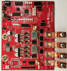
Image courtesy of:
Texas Instruments
Target solution 2 (2nd stage)
Solution for data centers
and communication equipment developed
by Texas Instruments
Design number: PMP21887
https://www.ti.com/tool/PMP21887
Responding to the large current required
by ASIC, etc., for the latest accelerators
and switches.
Specifications:14Vin max (12Vin typ)
- 0.85V 600A max
Controller IC: TPS536C7
Adopted Panasonic products
- ① SP-Cap
- Part number: EEFSX0D471E4
(2.5V,470μF,4.5mΩ,7.3x4.3xH2mm) - ② Hybrid capacitors
- Part number: EEHZA1V271P
(35V,270μF,20mΩ,ø10xH10.2mm)
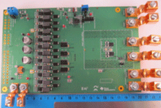
Image courtesy of:
Texas Instruments
Target solution 3
(Single-stage method + first stage of 2-stage method)
Solution for data centers
and communication equipment developed
by Texas Instruments
Design number: PMP4486
https://www.ti.com/tool/PMP4486
High-density high-efficiency conversion
from 48 V to the load voltage
and intermediate voltage
by using GaN.
Specifications:60Vin max (48V typ.)
- 1V 40A, 12V 10A, 29V 10A
Controller IC: UCD3138A
Adopted Panasonic products
- ① POSCAP
- Part number: 2TPE470MAJGB
(2V,470μF,11mΩ,3.5x2.8xH2mm) - ② Hybrid capacitors
- Part number: EEHZA1V680XP
(35V,68μF,35mΩ,ø6.3xH8mm) - ③ Aluminum electrolytic capacitor
- Part number: EEVFK1K101Q
(80V,100μF,320mΩ,ø12.5xH13.5mm)
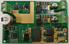
Image courtesy of:
Texas Instruments
Related product information
Tags related to this article
