Effects of Low ESR Capacitors on Low-pass Filters and Points to be Taken into Consideration
2018-02-19
- Characteristics of low-pass filters
- ESR of Capacitors and Attenuation Characteristics of Low-pass Filters
- Applications of Low ESR Capacitors for Smoothing Capacitors for Switching Power Supply Output and Points to be Taken into Consideration
- Effect of ESR on the Phase of LC filters
- Summery
- Related product information
- LC filter simulator
- Tags related to this article
In recent years, more electronic equipment use switching power supplies. Switching power supplies significantly contribute to high efficiency and miniaturization. On the other hand, noise from switching often becomes a major noise source. High-speed digital devices also propagate noise on power supply lines. These noises can deteriorate the measurement accuracy and S/N ratio particularly on equipment and devices that include analog circuits and therefore require management.
Characteristics of low-pass filters
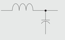
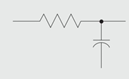
The diagrams below show relationships between the frequency and attenuation rate of each filter.
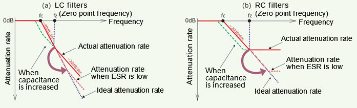
The LC filter, which is a secondary filter, attenuates at -40 dB/dec from the cutoff frequency fc. The ideal characteristic is to maintain this attenuation rate if the frequency increases. However, because zero point fz occurs due to the capacitance and ESR of the capacitor, an attenuation of +20 dB/dec is added after fz due to a primary advance, changing the attenuation rate to -20 dB/dec.
The RC filter, which is a primary filter, attenuates at -20 dB/dec from fc. Similarly, the ideal characteristic is to maintain this attenuation rate. However, an attenuation of +20 dB/dec is added after fz, offsetting the attenuation rate.
For both filters, the lower the ESR (equivalent series resistance) of the capacitor, the closer to the ideal attenuation characteristic will be because fz is determined by 1/(2π × Cout × ESR). In other words, fz shifts to a higher frequency, and the frequency range in which the ideal attenuation rate can be maintained will stretch to a higher frequency.
When the capacitance of a capacitor is increased, both fc and fz will be lower. If the amount of attenuation of noise is not within preferable levels, even when the capacitance is increased, the fz effect may be a factor.
ESR of Capacitors and Attenuation Characteristics of Low-pass Filters
Low-pass filters using LC and RC maintain high attenuation rates in higher frequencies when the capacitor’s ESR is lower. Actual characteristics will be shown using common aluminum electrolytic capacitors and electrolytic capacitors that feature low ESR.
Panasonic has a lineup of low-ESR electrolytic capacitors shown below that utilizes conductive polymer materials as electrolyte. Although each has features in addition to low ESR, OS-CON will be used here.

Aluminum polymer (Multilayer)
Ultra-low ESR capacitor, top in the industry

Tantalum polymer
Small, large capacity, and low ESR capacitor

Aluminum polymer (Wound)
High ripple, high pressure resistance, and low ESR capacitor

Aluminum hybrid (Polymer/Electrolyte)
Highly-reliable and high withstand voltage low-ESR capacitor
- ●Capacitor
-
- OS-CON (Part number 20SEP33M):
20VDC、33μF、ESR=37mΩ (Actual measurement value) - Aluminum electrolytic capacitor:
10VDC、33μF、ESR=1410mΩ (Actual measurement value)
- OS-CON (Part number 20SEP33M):
- ●Comparing LC filters (L = 10 μH)
-
OS-CON 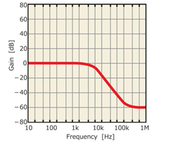
Aluminum electrolytic capacitor 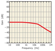
- ●Comparing RC filters (R = 5.6 Ω)
-
OS-CON 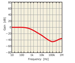
Aluminum electrolytic capacitor 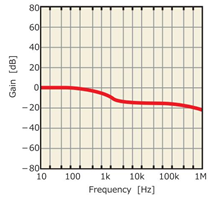
As you can see, OS-CON shows large attenuation rates in higher frequency ranges for both LC and RC filters over common aluminum electrolytic capacitors. It should be noted that these are the results of comparisons at normal temperature. At low temperatures (0ºC or lower), ESR of common aluminum electrolytic capacitors increases drastically, causing the attenuation rate to fall significantly. On the other hand, the ESR of OS-CON varies little even at low temperatures and can maintain high attenuation rates close to rates at normal temperature.
Applications of Low ESR Capacitors for Smoothing Capacitors for Switching Power Supply Output and Points to be Taken into Consideration
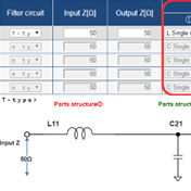
As shown in the circuit example on the right, the switching power supply output has a low-pass filter consisting of inductor L and capacitor Cout for smoothing the output voltage. For Cout to minimize the output ripple voltage, low ESR is important. Accordingly, the effectiveness of low ESR conductive polymer electrolytic capacitors shown above is highly evaluated.
However, because low ESR of Cout may cause the switching power supply output to be unstable and even oscillate in some cases, attention is required.
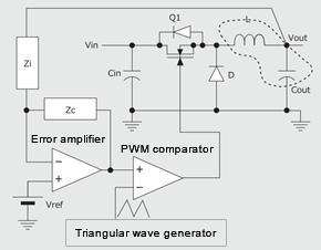
This circuit example is a schematic diagram of a voltage mode diode rectification step-down switching power supply. It shows that the output voltage is fed back to the error amplifier of the control circuit for stable control. It is well-known that the feedback loop tends to become unstable when there is no adequate phase margin, and it is the same with switching power supply circuits. It is the same idea for amplifier circuits that use operational amplifiers, etc. It is based on the relationship between poles and zeros in gain and phase characteristics. Phase margins may also need to be examined for those with feedback loops including linear regulators, irrespective of whether or not the conversion method shown in the example applies.
In short, oscillation occurs if a phase lag in a feedback loop reaches 360°. Phase margins of approx. 40° or more are usually considered necessary for stable control. The feedback of the circuit example is negative feedback and therefore has a phase lag of 180° to begin with. The phase lag due to the output LC filter within the loop is added on top of that. Accordingly, the operation might become unstable approx. after the phase lag of the LC filter exceeds 140° (Overall phase lag of 320°)
Effect of ESR on the Phase of LC filters
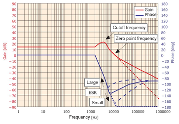
Although the relationship between the attenuation rate (Gain) of an LC filter and ESR of the capacitor is as described earlier, ESR also affects phase lags. The diagram on the right shows the gain (Attenuation rate) and phase characteristics of an actual LC filter in regards to frequencies. The ideal gains and phases are shown by the fine dotted lines.
For LC filters, which are secondary filters, a phase lag as an ideal characteristic is 180°. While this will cause oscillation simply when an LC filter is added in the negative feedback loop, it would not be ideal actually due to the zero point.
The phase lag starts from the cutoff frequency and continues until the zero point. It will advance from the zero point, until it has a 90° lag due to a primary advance by the capacitance and ESR of Cout (Blue solid line). Here, the key is the phase lag at the zero point.
The loop becomes unstable if the phase lag at zero point exceeds 140°, which can secure a phase margin of approx. 40°.
Zero point is determined by 1/(2π × Cout × ESR). If ESR becomes lower, the zero point frequency becomes higher and closer to the ideal characteristic, the phase lags by as much as, approximately 180°. In other words, if the phase margin becomes small, it can cause oscillation. Furthermore, variations in the characteristics of components and temperature changes require attention. When the phase margin is marginal, it might have a potential problem such as oscillating at low temperatures even if there is no problem at normal temperature.
This problem can be addressed by phase compensation of the feedback loop. The basic idea and method are almost the same as the phase compensation of common amplifier circuits. However, it may become more complex depending on the topology and control mode.
Most ICs in power supply circuits used for switching power supplies, are equipped with terminals for phase compensation. Some types of ICs have phase compensation circuits mounted and do not require external compensation. Basically, the datasheet or design manual of the power supply IC to be used indicates its phase compensation method. Necessary components consist of several resistances and capacitors.
Because it is difficult to simply measure the loop frequency characteristics of power supply ICs, common phase compensation is carried out through the optimization of load transient response characteristics. This only requires a load device and an oscilloscope. It is pragmatic and relatively easy because start standard circuits and component constants are also provided. If you have a frequency response analyzer (FRA), you can make adjustments while measuring the actual frequency characteristics.
Summery
Because switching power supplies and high-speed logic devices can be noise sources, LC filters and RC filters are used as one of the ways for noise management. For both of them, the ESR of the capacitor to be used and filter performance are related, and the use of low ESR capacitors enables the attenuation characteristics of the filter to be closer to ideal. Panasonic conductive polymer electrolytic capacitors, with their low ESR, are effective options.
Meanwhile, for Cout, which is an output smoothing filter for switching power supplies, low ESR is an essential requirement for ripple voltage reduction. Low ESR conductive polymer electrolytic capacitors are an also effective solution to this. However, Cout with low ESR has the possibility of making the output of switching power supplies unstable, which requires attention. This problem can be addressed with phase compensation for the feedback loop of power supplies. Because power supply circuits that use power supply ICs have phase compensation terminals at power supply ICs in many cases, adjustments are relatively easy. With these points taken into consideration, it is possible to design switching power supplies with small output ripple voltages.
Related product information
LC filter simulator
The Industrial & Automotive use LC filter simulator enables the simulation of attenuation amounts when configuring a filter using Panasonic's power inductor and aluminum electrolytic capacitor suitable for industrial & automotive use.
Tags related to this article

This document summarizes the LC filter-related articles posted as technical information for the Optimal Solutions for Circuit Design.
