Power System Inductor: Excellent Characteristics for the Metal Composite Type
2017-10-23
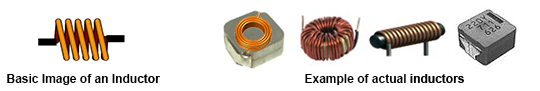
What Is an Inductor?
An inductor is an important passive component used in parallel with a resistor (R) and capacitor (C). “L” is used as the inductor symbol. The symbol “L” is said to come from “Lenz Law” relating to electro-magnetic induction (Other explanations also exist). The basic structure is a conductor wound in a coil shape that converts electrical energy to magnetic energy, storing it inside the inductor. The quantity of magnetic energy to be stored is determined by inductance, and the unit henry (H).
Basic Characteristics of an Inductor
Inductors have the following basic characteristics.
- Current flows to generate a magnetic field, and a change of the magnetic field generates an opposing current.
- Changes electrical energy to magnetic energy and stores it.
- DC can pass through but AC cannot easily pass through at higher frequencies.
① and ② are related characteristics. Current that flows in an inductor generates a magnetic field, but the magnetic flux remains after the current flow stops. This is due to the inductor being magnetized. In other words, an inductor can store electrical energy as magnetic energy.
The characteristics of ③ work as a conductor when DC is applied, but with AC, the higher the frequency, it becomes more difficult to flow through. This characteristic comes from the impedance of the inductor.
- Impedance (Z) of an inductor is expressed by the following formula.
- Z = R + j (2πf L)
- In addition, the absolute value of impedance can be calculated by the following equation.
- |Z| =√ R2+(2πf L)2
- Z
- Impedance [Ω]
- R
- DC resistance component [Ω]
- j
- Imaginary number
- π
- Circular constant (3.14)
- f
- Frequency [Hz]
- L
- Inductance [H]
Judging from this equation, the higher the frequency, the larger the impedance and more difficult it is for current to flow. Also, with larger inductance L, current becomes more difficult to flow.
Basic Structure of an Inductor and Inductance
The most basic inductor is a conductor wound in a coil shape with both ends being external terminals. In recent years, the majority of inductors utilize a core with a conductor wound around it.
Inductance of an inductor can be obtained by
using the following formula.
kμSN2
l
- L
- Inductance [H]
- k
- Nagaoka coefficient
- μ
- Permeability of a core [H/m]
- N
- Number of coil turns
- S
- Cross-section of the coil [㎡]
- l
- Coil length [m]
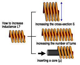
From this formula, it is understood that inductance gets larger by 1) increasing the cross-section S, 2) increasing the number of turns, and 3) increasing permeability by inserting a core.
Principal Function of an Inductor
How an inductor works in a real application? Specific example is shown by using the basic characteristics ①、②、③ of the inductor described earlier.
① Current flow generates a magnetic field, and a change of the magnetic field generates an opposing current ⇒Transformer principle
The structure with 2 windings of the primary and secondary sides can be interpreted as a transformer. Supplying current in the primary winding generates a magnetic field, and the magnetic field generates current in the secondary winding. Voltage can be converted by setting a winding ratio of the primary and secondary windings.

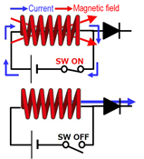
② Changing electrical energy into magnetic energy for storing ⇒ Principle of a choke coil
Example of inductors used for DC/DC converter. By turning on the switch and suppling current to the inductor, a magnetic field is generated and the energy is stored in the inductor in the form of magnetic energy.
By turning off the switch to stop current supply, the stored magnetic energy is released (change of the magnetic field) and current flows.
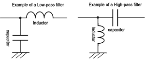
③ DC can pass through but AC cannot easily pass through at higher frequencies. ⇒ Filter function
By utilizing the ability to change the difficulty of AC flow, based on the change of impedance by frequency, a low-pass filter or high-pass filter can be configured in conjunction with a capacitor.
Principal Specification for an Inductor
Principal specifications and performance for an inductor is shown here. Because the specified condition varies by manufacturer and product, the notes in the data sheet need to be checked.
| Specification Items | Specified condition |
|---|---|
| Inductance(L value)[μH] | Based on the measured frequency (100 kHz) |
| DC resistance(DCR)[Ω] | Resistance component of the conductor (copper wire) comprising the inductor |
| Rated current: Temperature rise(ΔT)[A] | Rated current value when the temperature rise reaches 40K by applying DC current |
| Rated current: DC superimposed(ΔL)[A] | Rated current value when the L value reduces by 30% from the initial value by applying DC current (DC superimposed) |
Types of Inductor
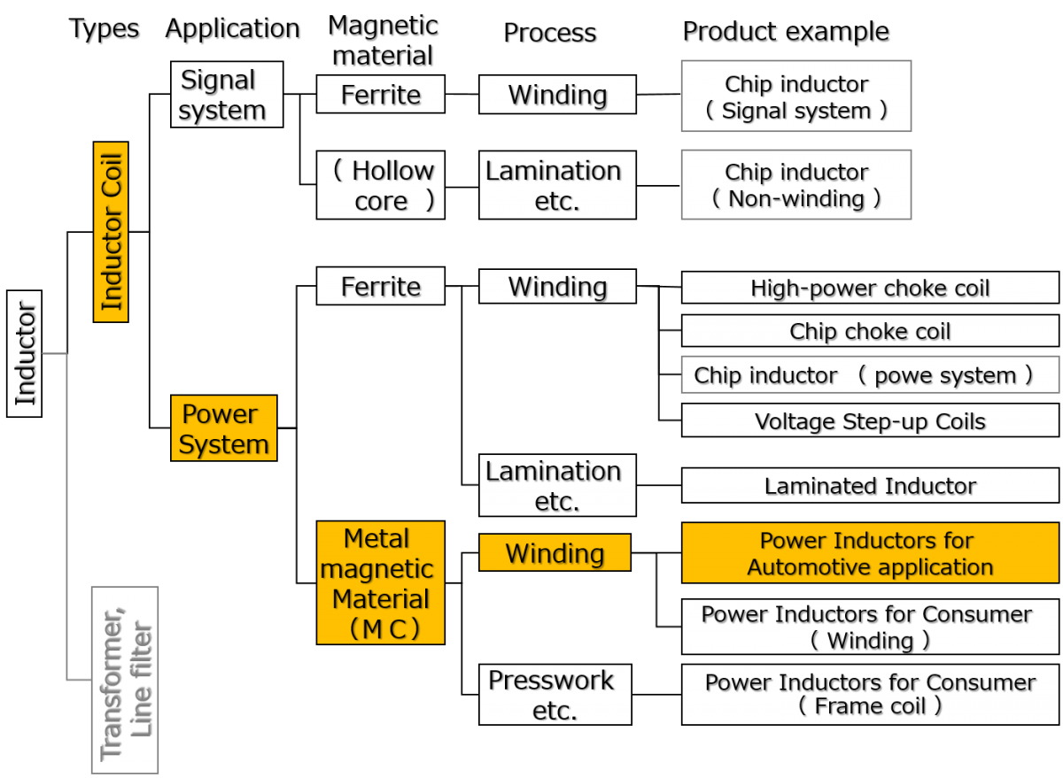
A wide variety of inductor types are used. The method of grouping varies by the viewpoint. The chart shown below is the classification made by application to the signal system and power system, and by magnetic (core) material and process.
In this chart, power system inductors have been becoming one of the key items toward the market demand for larger capacity, higher efficiency and compact sizing required for power supplies in recent years. Although ferrite material is used widely for magnetic (core) material of power system inductors, metal composite type power inductors utilizing metal magnetic material for the core are getting market attention as a solution to the problems in power system applications in recent years.
What is a Metal Composite Inductor?
Metal composite (hereinafter MC) type is currently deployed to power system applications, such as DC/DC conversion of power supply circuits and input filters.
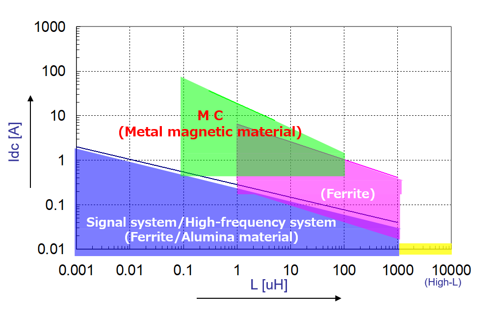
The chart shown below describes the coverage of inductance and allowable current (Idc) for power system MC type, ferrite type, and signal system/high-frequency system inductors.
This chart indicates that the MC type can handle a larger current compared to the ferrite type.
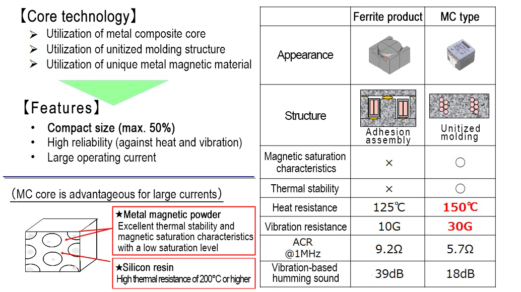
Features of Metal Composite Type
Panasonic MC type power inductors achieve automotive-level high reliability, compact size, and large current capacity compared with ferrite types by incorporating unique metal magnetic material and unitized molded structure.
As shown by the comparison table with ferrite types below, metal composite types are superior in the essential characteristics of inductors such as magnetic saturation characteristics, thermal stability, heat resistance, vibration resistance, ACR (AC resistance), and vibration-based humming sounds.
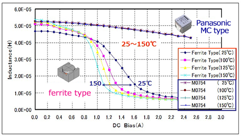
Magnetic saturation characteristics and thermal stability
Magnetic saturation characteristics (=DC superimposed characteristics) of MC type and ferrite type plotted by temperature condition at 25°C, 100°C, 125°C, and 150°C are shown as an example. Magnetic saturation characteristics refer to the tendency of generation of magnetic saturation and rapid reduction of inductance at a certain current value when DC is applied to an inductor. It is one of the important characteristics shown in the “Principal Specifications”.
In general, ferrite type is well known to have noticeable saturation characteristics and as shown by the graph, when the DC bias is increased, inductance suddenly drops and the saturation characteristics change with temperature. In contrast, Panasonic MC type does not generate rapid inductance reduction typical of saturation, and the characteristics do not change much with temperature. This is an important point in regards to fluctuations due to ambient temperature, and particularly important for heat generating power system inductors.
saturation characteristics and thermal stability
Heat resistance, vibration resistance
Panasonic MC type inductors provide high reliability in automotive applications ensured through strict reliability tests. Reliability is warranted for heat shock:-40℃⇔150℃/2000 cycle, and heat resistance of 150℃/2000 hours. Shown below are the standard automotive application test items and condition.
| Test item | Condition | Test count/time | Judgment criteria | |
|---|---|---|---|---|
| Heat shock test | -40/+150℃ (Each 10Minutes) |
2000 cycles |
|
|
| Vibration test | 10G(5Hz ~ 2kHz) | XYZ (each 4 hours) | ||
| 30G(5Hz ~ 2kHz) | ||||
| High-temperature life test | 150℃, DC Rated A | 2000 hours | ||
| Temperature-controlled life test | 85℃/85℅RH Rated current | 2000 hours | ||
| Cold resistance test | -40℃ | 2000 hours | ||
*Preprocessing condition: 85±2℃, 85℅RH, 168 h, then reflow aging 3 times
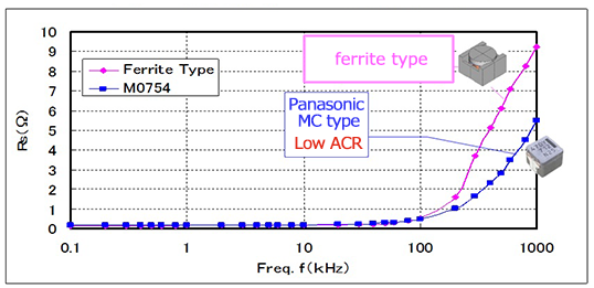
AC resistance (ACR)
When the frequency of the current in the conductor is increased, current flow concentrates on the conductor surface due to the skin effect and proximity effect, thereby making the center part low density and surface part high density. This increases the resistance component with a higher frequency, and in an inductor, this increased resistance component is called AC resistance (ACR).
The graph shown below is a comparison of AC resistance (ACR) between the MC type and ferrite type. Increased frequency increases ACR and increased AC loss increases heat generation. As shown in the graph, increase of ACR of the MC type is smaller than that of the ferrite type, therefore, loss=heat generation is smaller at high frequency.
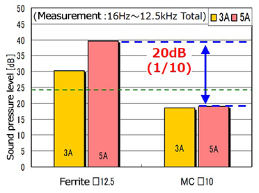
Vibration-based humming sound
Inductors sometimes generate mechanical vibration-based humming sound through condition and structure. In order to ease the rapid saturation of a core, an air gap is often utilized in a ferrite core, and this air gap is one of the causes of vibration-based humming sound. Panasonic MC type is made with unitized molded structure without an air gap (refer to the structure diagram “Features of Metal Composite Type”), thereby making the vibration-based humming sound much smaller. In comparison with the ferrite type, sound is approx. 20 dB or 1/10.
when driven in an audible frequency
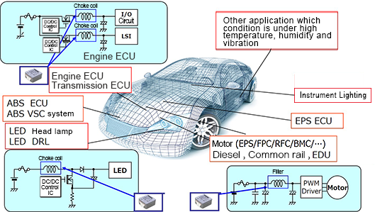
Metal Composite Type Application and Future
As the MC type provides excellent characteristics and high reliability as described above, it is widely used for automotive applications. In principle, it us used for DC/DC converter and input filter of power supply circuit in a variety of ECU.
Panasonic intends to expand the variability of the MC type and deploy in other automotive applications in the future.
Related product information
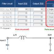
LC filter simulator
The Industrial & Automotive use LC filter simulator enables the simulation of attenuation amounts when configuring a filter using Panasonic's power inductor and aluminum electrolytic capacitor suitable for industrial & automotive use.
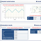
Power Inductor loss simulator for automotive application
The Power Inductor loss simulator for automotive application enables the simulation of losses and temperature rises according to the current for Panasonic’s power inductors designed for automotive use.
Tags related to this article

This document summarizes the LC filter-related articles posted as technical information for the Optimal Solutions for Circuit Design.
