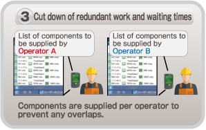
High-quality placement - APC system
Controls variations in PCBs and components, etc. on a line basis to achieve quality production.
APC-FB*1
Feedback to the printing machine
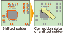
- Based on the analyzed measurement data from solder inspections, it corrects printing positions. (X,Y,θ)
APC-FF*1
Feedforward to the placement machine
APC-MFB2
Feedforward to AOI /
Feedback to the placement machine
- It analyzes solder position measurement data, and corrects component placement positions (X, Y, θ) accordingly.
Chip components (0402C/R ~)
Package component (QFP, BGA, CSP)
- Position inspection on APC offset position
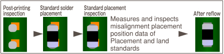
- The system analyzes AOI component position measurement data, corrects placement position (X, Y, θ) , and thereby maintains placement accuracy.
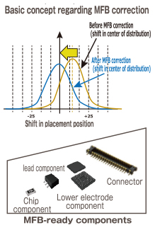
Compatible with chip components, lower electrode components and lead components*2
*1 : APC-FB (feedback) /FF (feedforward) : 3D inspection machine of another company can be also connected. (Please ask your local sales representative for details.)
*2 : APC-MFB2 (mounter feedback2) : Applicable component types vary from one AOI vendor to another. (Please ask your local sales representative for details.)
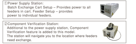
Component Verification option - Off-line setup support station
Prevents setup errors during changeover Provides an increase of production efficiency through easy operation
*Wireless scanners and other accessories to be provided by customer
- Preemptively deters component misplacement
Prevents misplacement by verifying production data with the barcode information on changeover components. - Automatic setup data synching function
The machine itself does the verification, eliminating the need to select separate setup data. - Interlock function
Any problems or lapses in verification will stop the machine. - Navigation function
A navigation function to make the verification process more readily understandable.
With the support stations, offline feeder cart setup is possible even outside of the manufacturing floor.
- Two types of Support Stations are available.
Changeover ability - Automatic changeover option
Supporting changeover (production data and rail width adjustment) can minimize time loss
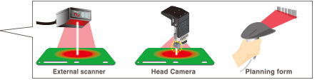
- PCB ID read-in type
PCB ID read-in function is selectable from among 3 types of external scanner, head camera or planning form
Changeover ability - Feeder setup navigator option
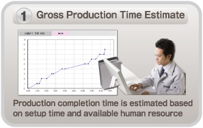
It is a support tool to navigate efficient setup procedure. The tool factors in the amount of time it takes to perform and complete setup operations when estimating the time required for production and providing the operator with setup instructions.
This will visualize and streamline setup operations during setup for a production line.
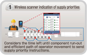
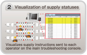
Operating rate improvement - Parts supply navigator option
A component supply support tool that navigates efficient component supply priorities. It considers the time left until component run-out and efficient path of operator movement to send component supply instructions to each operator. This achieves more efficient component supply.
*PanaCIM is required to have operators in charge of supplying components to multiple production lines.
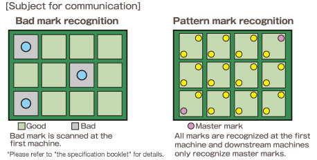
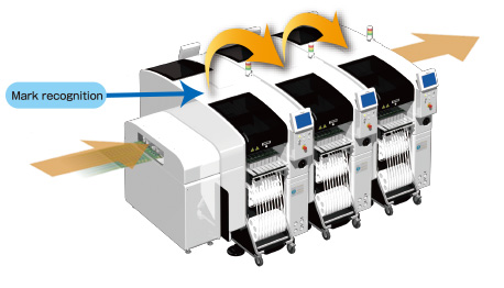
PCB information communication function
Information of mark recognitions done on first NPM machine in line is passed on to downstream NPM machines.
Which can reduce cycle time utilizing the transferred information.
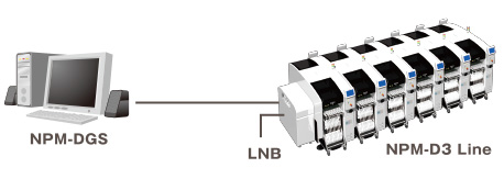
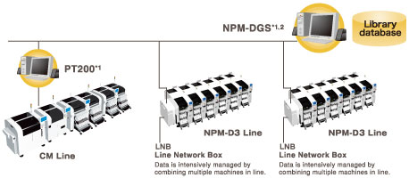
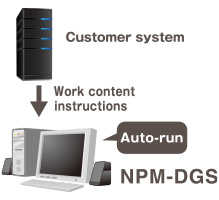
Data Creation System - NPM-DGS (Model No.NM-EJS9A)
This is a software package that provides integrated management of component library and PCB data, as well as production data that maximizes mounting lines with high-performance and optimization algorithms.
*1:A computer must be purchased separately.
*2:NPM-DGS has two management functions of floor and line level.
CAD import
Allows you to import CAD data and check polarity, etc., on the screen.
Optimization
Realizes high productivity and also allows you to create common arrays.
PPD editor
Update production data on PC during production to reduce the loss of time.
Component library
Allows unified management of the component library including mounting, inspection and dispensing.
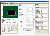
Data Creation System - Offline Camera (option)
Component data can be created offline even while the machine is in operation.
Use the line camera to create component data.
Lighting conditions and recognition speed can be confirmed in advance, so it contributes to the improvement of productivity and quality.
Offline Camera Unit
Data Creation System - DGS Automation (option)
Automated manual routine tasks reduce operation errors and data creation time.
Manual routine tasks can be automated.
By collaborating with the customer system, the routine tasks for creating data can be reduced, so it contributes to a significant reduction in production preparation time.
It also includes the function to automatically correct the coordinates and angle of the mounting point (Virtual AOI).
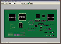
Example of entire system image
Automated tasks (excerpt)
- CAD import
- Offset mark setting
- PCB chamfering
- Mounting point misalignment correction
- Job creation
- Optimization
- PPD output
- Download
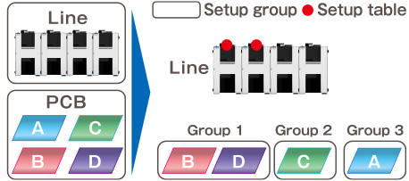
Data Creation System - Optimization of setup (option)
In production involving multiple models, setup workloads are taken into account and optimized.
For more than one PCB sharing common component placement, multiple setups may be required due to a shortage of suppy units.
In order to reduce the required setup workloads in such a case, this option divides PCBs into similar component placement groups, selects a table (s) for setup and thus automates component placement operation.
It contributes to improving setup performance and reducing production preparation time for customer manufacturing various kinds of products in small quantities.
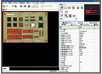
Example
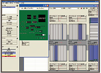
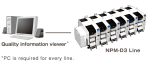
Quality improvement - Quality information viewer
This is software designed to support a grasp of changing points and analysis of defect factors through the display of quality-related information (e.g., feeder positions used, recognition offset values and parts data) per PCB or placement point. In case of our inspection head introduced, the defect locations can be displayed in association with quality-related information
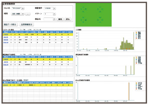
Quality information viewer window
Example of use of quality information viewer
Identifies a feeder used for mounting of defect circuit boards. And if, for example, you have many misalignments after splicing, the defect factors can be assumed to be due to;- splicing errors (pitch deviation is revealed by recognition offset values)
- changes in component shape (wrong reel lots or venders)