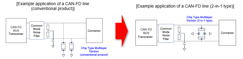
On-board CAN-FD compatible "Chip Type Multilayer Varistor 2-in-1 Type"
2025-01-17

Memberships: The Ceramic Society of Japan, The Institute of Electrostatics Japan, Society of Automotive Engineers of Japan.
Publications: Transactions of Society of Automotive Engineers of Japan (Vol. 55, No. 1, January 2024).
- Features
- The 2-in-1 structure reduces the capacitance difference to 1.0 pF or less, and realizes a high communication signal quality.
- Achieves both high ESD protection and EMC performance (ensures high communication stability through EMC testing)
- Reducing the number of parts contributes to reduction of material and energy used in customers' processes
- Application
- Specifications
- Related information
- Tags related to this article
As the speed of in-vehicle communication has been increasing due to the digitalization of cars in recent years, the generation of noise and the deterioration of communication quality caused by the capacitance difference between High and Low lines on the CAN-FD differential transmission become an issue. Furthermore, many vehicles are being equipped with an increasing number of ICs of process sensors and positional information, which increases the current flowing through on-board harnesses and raises the demand for EMC (electromagnetic compatibility) performance from on-board equipment.
In response to this, we have developed a "Chip Type Multilayer Varistor 2-in-1 Type" for automotive use, which combines the varistor functions of two elements into one while maintaining high ESD protection performance, by taking advantage of varistor materials technologies and multilayer chip component design capabilities that we have cultivated over many years.
Features
- The 2-in-1 structure reduces the capacitance difference to 1.0 pF or less, and realizes a high communication signal quality.
- Achieves both high ESD protection and EMC performance (ensures high communication stability through EMC testing)
- Reducing the number of parts contributes to reduction of material and energy used in customers' processes
1. The 2-in-1 structure reduces the capacitance difference to 1.0 pF or less, and realizes a high communication signal quality.
In conventional ESD countermeasures for differential transmission lines such as CAN and CAN-FD, chip-type multilayer varistors are individually placed on the High and Low sides of the transmission line. Therefore, it has been difficult to ensure the stability of signal quality in high-speed communications due to the influence of individual capacitance differences.
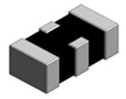
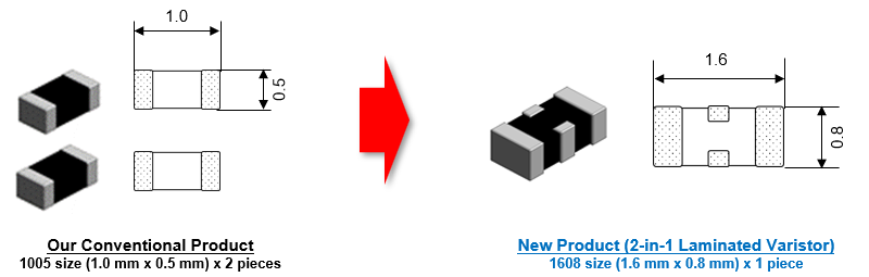
Our new product has a unique 2-in-1 structure and process design. By actualizing the ESD countermeasure function for two lines in one 1608 size component, the difference in capacitance between High and Low lines of the differential transmission has been suppressed to 1.0 pF or less (1/5 or less compared with two conventional products of our company being used), and a high communication quality is realized.
2. Achieves both high ESD protection and EMC performance (ensures high communication stability through EMC testing)
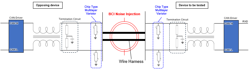
The new product is based on the varistor material developed by our company in 1968 and has been improved to have a high ESD protection performance (25 kV, 10 times @150 pF, 330 Ω). Conventional Zener diodes tend to cause a communication error in a BCI test, which is a type of EMS test. However, this new product can maintain high communication stability in the same test.
Using a CAN-FD evaluation board, prepare a sample with the same configuration and specification on the daughter board and make it communicate with the opposing device. Then, check for the existence of any communication error due to BCI noise and observe the waveform of CAN-H/L and Rxd.
EMC test conditions:1MHz~505MHz/200mA
Injection time: 2 seconds
Injection frequency: 1 Injection point: 150 mm from the ECU
CAN-FD communication :Communication rate 5 Mbps
| Test Sample | Test Results (Presence or Absence of a Communication Error) |
|
|---|---|---|
Chip Type Multilayer Varistor |
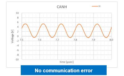 |
Pass |
Zener Diode (for CAN-FD) |
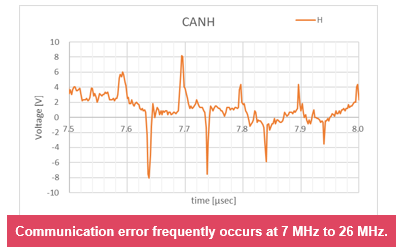 |
Fail |
3. Reducing the number of parts contributes to reduction of material and energy used in customers' processes
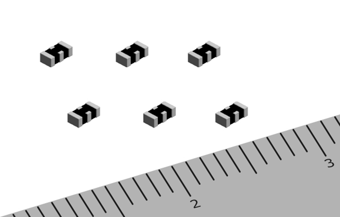
When using one new product (1608 size: 1.6 mm x 0.8 mm), the number of mounting parts can be reduced by half, while the performance is the same as when our two conventional products (1005 size: 1.0 mm x 0.5 mm) are used. By reducing the number of parts, packaging materials used in the customer's assembly process and energy used in packaging are reduced, contributing to the reduction of environmental impact.
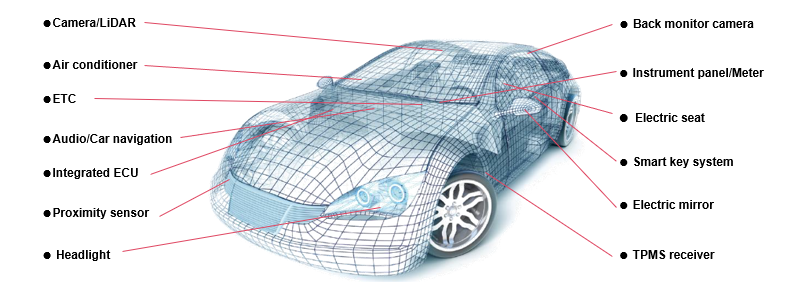
Application
Specifications
| Product number | EZJPRV270RM |
|---|---|
| Maximum allowable circuit voltage | DC 16V |
| Varistor voltage | 27V (24.3 ~ 32.4V) |
| Capacitance | 15pF±3.0pF@1MHz |
| Capacitance difference | 1.0pF max. |
| Clamping voltage | 60V max. |
| ESD resistance | IEC61000-4-2 150pF/330Ω Contact discharge 25kV |
Relates articles
Tags related to this article