Processor Basics (4) - Key Characteristics Required for Inductors and Capacitors -
2026-10-28

In the previous article, we introduced in detail the overview and design of power supplies, which are essential for processor operation. This article focuses on the detailed specifications of power supplies for processors and explains the key characteristics required of the inductors and capacitors used to meet those specifications.
1. Specifications of Power Supplies for Processors
To understand the premise, let us first look at trends in processor power requirements.
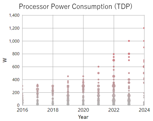
Processor power consumption is often published as part of product specifications. When plotted over time, it is clear that power levels have been increasing at a faster pace in recent years, as shown in the figure below. As explained in Processor Basics (1): Elements That Determine Performance and Trends, this is because higher performance is required to process larger volumes of data. In particular, processors used in data center and telecom infrastructure, smartphones, PCs, graphics cards, and other applications continue to reach new peak values.

However, when selecting components for a power supply that meets processor requirements, power consumption values alone are not sufficient.
It is necessary to understand the voltage and current specifications required for processor operation. The following are some examples.
| Processor (Core Rail) |
Voltage | Current | ||||
|---|---|---|---|---|---|---|
| Operating Voltage(Nominal) | Voltage Tolerance | Continuous Maximum Current (TDC) | Instantaneous Maximum Current (EDC.) | Maximum Current Step (Istep) | Load Current Slew Rate | |
| High Performance GPU / ASIC |
0.7V | ±3% of operating voltage | 600A | 1000A | Approx. 50% of EDC | 500A/us |
| High Performance CPU |
1.8V | ±5% of operating voltage | 250A | 500A | Approx. 80% of EDC | 1000A/us |
| High Performance FPGA |
0.8V | ±3% of operating voltage | 200A | 300A | Approx. 50% of EDC | 200A/us |
| High Performance Automotive SoC |
0.8V | ±3% of operating voltage | 60A | 100A | Approx. 50% of EDC | 100A/us |
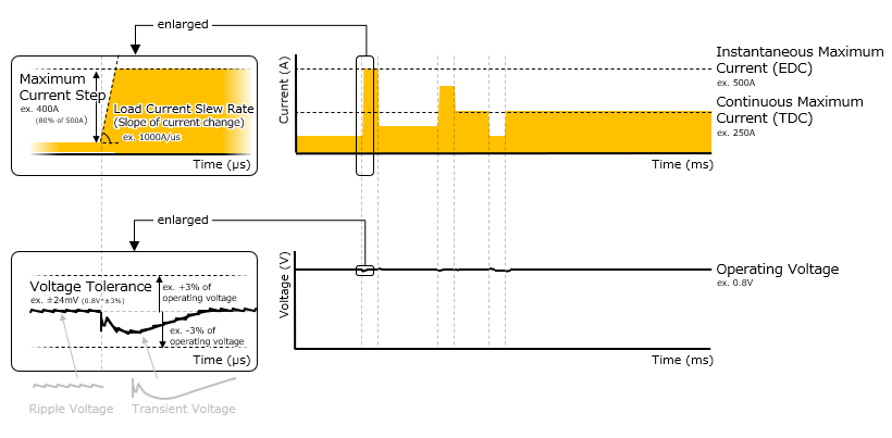
First, regarding voltage, the core rails, which perform the main computational processing in any type of processor, operate uniformly at a very low voltage. In the 1970s, they operated at 5 V, but with the progress of transistor miniaturization, it is now common for them to operate at 1 V or lower. Because processors can allow only a few percent of voltage tolerance to operate normally, they now require a more stable voltage supply with smaller fluctuations than when 5 V was used.
| Operating Voltage | The voltage required for processor operation. A single processor is usually divided into circuits by function, and each circuit requires individual operating-voltage control. |
| Voltage Tolerance | The allowable voltage range, typically within a few percent of the processor operating voltage. If this range is exceeded, malfunction or failure may occur. |
| Voltage Fluctuation (Voltage Change) | In actual operation, the voltage output from the power supply to the processor is subject to DC voltage fluctuations caused by output-voltage accuracy and copper trace voltage drop, as well as AC voltage fluctuations caused by switching and load transients. The design must ensure that these fluctuations do not exceed the voltage tolerance under the worst-case processor operating conditions. Usually load transients are the factor causing largest voltage fluctuation. |
Next, regarding current, the required current is not uniform. Depending on the application and required performance grade, currents ranging from several amperes to several hundred amperes are required. For the highest-performance processors used in AI and network equipment, current requirements are approaching the thousand-ampere range. In the 1970s, processor current was only several hundred milliamperes, showing how dramatically current levels have increased. This is because processor circuit scale has expanded to support applications that require faster computation, driving enormous numbers of logic transistors simultaneously.
Looking more closely at processor current specifications, maximum current is specified separately as continuous and instantaneous values. Although both values tend to increase, care must be taken not to confuse them. Processor current also commonly experiences random, high-speed, large-current load transients according to changes in computational load. Compared with earlier processors, both the amplitude and speed of transients are increasing. The maximum current change at the largest load transient is called maximum current step. Please note that even if two different processors have the same continuous maximum current, each maximum current step can often differ, resulting in need of different power supply designs. Therefore, it is important to understand such overall behavior of processor current.
| Continuous Maximum Current (TDC) | The maximum current at which the processor can operate continuously. With the recommended thermal design, the processor can operate safely for a long period. For this reason, it is called Thermal Design Current, or TDC. It corresponds to TDP, or Thermal Design Power, commonly published as processor power consumption, with the voltage component removed. TDP = TDC x operating voltage. |
| Instantaneous Maximum Current (EDC, Ipeak, Imax) | The maximum current at which the processor can operate instantaneously. This enables the processor to deliver short-term peak performance. It is also called Electrical Design Current, or EDC, or peak current (Ipeak, Imax), and represents the electrical upper limit of processor current. This value is usually larger than TDC. It is allowed only for a short period of several to several tens of milliseconds. |
| Maximum Current Step (Istep) | The maximum amplitude of load transients that occurs during processor operation. It varies depending on the behavior of the application being processed by the processor. For example, in CPUs used in PCs and servers, computational load increases sharply when multiple applications are launched from an idle state, causing a large current step up. |
| Load Current Slew Rate | The speed of processor current step. Even when the maximum current step is the same, the slew rate becomes higher as more instantaneous processing is required. It varies depending on application behavior and processor architecture. |
2. Key Characteristics Required for Inductors and Capacitors
Now then, to meet these requirements, what characteristics are especially important for inductors and capacitors used in processor power supplies? As noted above, processors as loads require highly accurate low voltage and dynamic large current compared with other loads. Therefore, two points are particularly important in power supply design: (1) reducing power loss, or achieving high efficiency, and (2) suppressing voltage fluctuation, or achieving high stability. In many cases, inductors contribute especially to the first point, while capacitors contribute especially to the second. The following sections explain these roles and the characteristics required.
2-1. Inductor
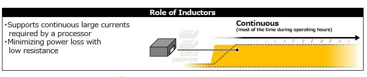
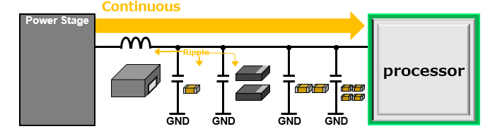
The role of the inductor is to work together with the power stage to convert input current into a large current and continuously supply current to the processor. Instantaneous fast current supplies are handled by capacitors, as described later.
In a typical DC/DC converter, current continuously flows through the inductor and the power stage.
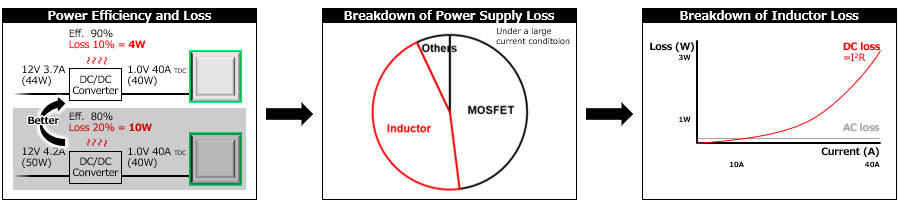
In an ideal power supply, power loss would be zero no matter how much current flows, meaning 100% efficiency. For example, a 1.2 V / 100 A output could be obtained from a 12 V / 10 A input. In real power supplies, however, this is not the case. Efficiency is usually in the 80% to 90% range. Because the components in a DC/DC converter have resistive elements, power loss occurs.
Increasing processor current is generally addressed by increasing the number of phases in a multiphase design, in other words, by increasing the number of power stage and inductor pairs connected in parallel. Because the phases operate alternately, increasing the number of phases distributes the load per phase and reduces losses. Even so, total loss tends to increase as current rises, so reducing the resistance of the components themselves is effective because it allows more current per phase.
Problems Caused by Large Power Loss
|
Looking at a typical loss breakdown of DC/DC converter components under high-current conditions, conduction loss in the power stage and inductor accounts for most of the loss. Conduction loss can be roughly expressed by the following formula.
P = I2 x R … Power loss (W) = Current (A)2 x Resistance (Ω)This formula shows that loss increases rapidly as current rises. Inductor losses can be broadly divided into DCR, or DC resistance, and ACR, or AC resistance. Under high-current conditions, DCR is the more critical factor. ACR loss ratio can be larger at low current and increases with higher switching frequency. In contrast, DCR loss increases significantly with larger current according to the formula above. Therefore, low DCR is a particularly important characteristic for processor power supplies, which often operate at high current.
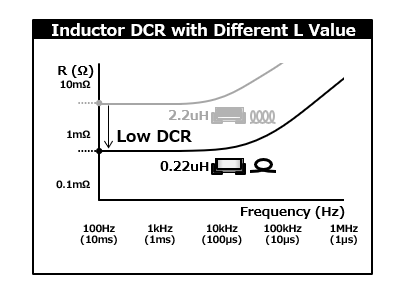
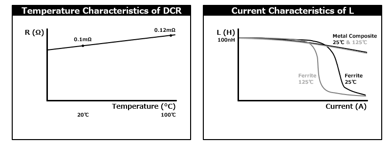
The DCR of an inductor can be reduced by using a lower inductance(L) value, because low-L inductors have physically shorter windings. For this reason, processor power supplies commonly use low-L inductors in the range of several hundred to several tens of nH, and products with low DCR in the 1 mΩ to 0.1 mΩ range are available.
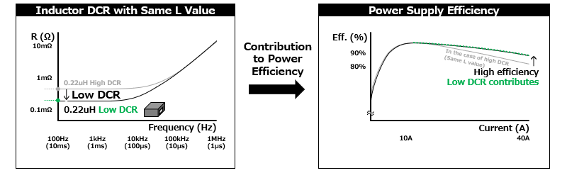
For products with the same L value, DCR is reduced through methods such as those shown below.
| Low DCR |
|
By achieving low DCR in this way, inductors contribute to reducing power loss under high-current conditions, which is especially important for processors.
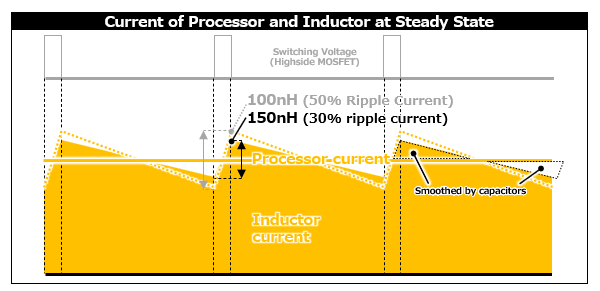
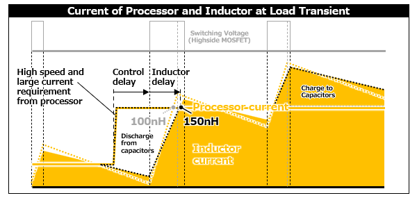
As described above, low-L-value inductors are selected to achieve low DCR. Selecting a low L value provides another major advantage for processor power supplies. That is improved power supply response. In other words, lower inductance makes the slope of inductor current steeper, enabling current to be supplied to the processor more quickly. This can reduce the total capacitance required. However, the L value should not be made endlessly lower. If the L value is too low, ripple current becomes excessively large, making AC loss and EMC noise non-negligible and causing power-supply operation issues such as unwanted over current protection activation. For this reason, it is generally recommended to select an L value that keeps the inductor ripple current at no more than 30% of the continuous maximum current (TDC).
| High L Value |
|
| High L Value |
|
When selecting an inductor, attention must also be paid to current ratings. Inductor specifications commonly define a temperature-rise rated current (Itemp) and a DC superposition rated current (Isat).
For Itemp, it is necessary to select an inductor that exceeds the continuous maximum current per phase and can achieve the target efficiency. Itemp is defined as the current value at which the inductor temperature rises by 40°C, but measurement conditions vary by manufacturer, so it must be confirmed that the temperature does not rise beyond the allowable range under the actual operating conditions of the application.
For Isat, it is necessary to select an inductor that exceeds the instantaneous maximum current per phase. Isat is defined as the current value at which the inductor saturates and its inductance decreases significantly, typically by 30%. If current exceeding the Isat flows, the inductance may fall below the allowable level, causing too large ripple current and creating risks such as reduced efficiency, malfunction, or failure.
In addition, depending on the type and product of the inductor, characteristics may vary significantly due to factors such as current and temperature. Therefore, it is important to check these characteristic changes and design with sufficient margin.
2-2. Capacitor
The role of capacitors is to instantaneously supply current when the processor requires a rapid current increase. Conversely, when the processor suddenly no longer requires current, capacitors also absorb the excess current flowing from the inductor.
In the operation of a typical DC/DC converter, the current supplied from the inductor cannot keep up with the speed of the current step required by the processor. This is because there is a delay caused by the controller’s feedback control, followed by a delay caused by the inductor current slope. Therefore, in actual designs, capacitors supply current to the processor until current from the inductor catches up. Because capacitors have impedance(Z), voltage fluctuation occurs according to the magnitude of the current capacitors supply. The same applies when capacitors absorb current that the processor no longer requires.
Even as processor current continues to increase year by year, voltage fluctuation must be stabilized within a voltage tolerance range of only a few percent of the operating voltage. For this reason, reducing impedance of capacitors inevitably becomes important.

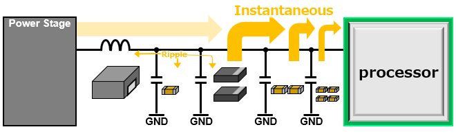
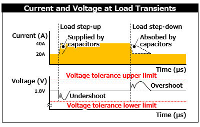
| Load Step When computational processing suddenly increases, the processor requires current instantaneously. → Due to delays in the feedback control and inductor current slope, the power supply cannot provide current instantaneously. → Instead, Capacitors supply the required instantaneous current. → The capacitors’ impedance causes a transient voltage drop (=undershoot). → The voltage recovers as continuous current from the inductor catches up. |
| Load Step-down (Load Release) When computational processing suddenly decreases, the processor rejects current instantaneously. → To reduce current, the power supply temporarily stops, but due to delays in the feedback control and the inductor current slope, it cannot stop supplying current instantaneously. → Capacitors absorb the excess current. → The capacitors’ impedance causes a transient voltage rise (=overshoot). → Once current has decreased to the required level, the power supply restarts and maintains the operating voltage. |
Problems Caused by Insufficient Voltage Stability
|
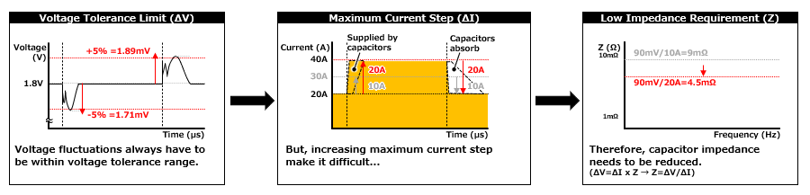
Voltage fluctuation caused by load current step and capacitor impedance can be roughly expressed by the following equation, based on Ohm’s law.
ΔV = ΔI x Z … Generated voltage fluctuation (V) = Current step (A) x Impedance (Ω)
This equation shows that the lower the capacitor impedance, the smaller the voltage fluctuation can be made.
Let us rearrange the equation to estimate the target impedance requirement.
Z = ΔV ÷ ΔI … Required impedance (Ω) = Voltage Tolerance (V) ÷ Current step (A)
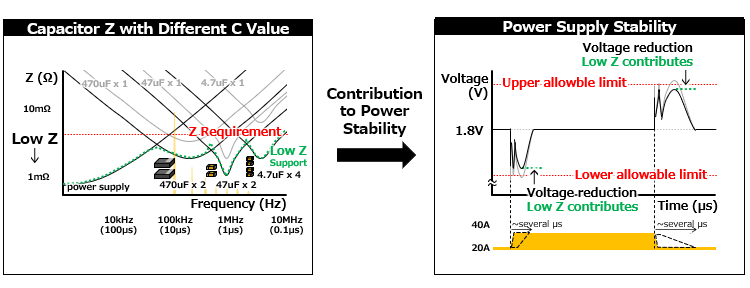
For example, if the operating voltage is 1.8 V, the voltage tolerance is within ±5%, and the current step is 20 A, then ΔV = 1.8 V x ±5% = ±30 mV, and Z = Δ30 mV ÷ Δ20 A = 4.5 mΩ.
This calculation provides 4.5 mΩ as a rough target for the impedance requirement*.
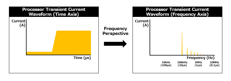
- * Because current step waveform can be decomposed into frequency components, the impedance that matters strictly can differ by frequency.
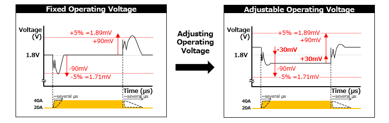
However, when adjustable operating voltage methods, such as LLC (Load Line Calibration) or AVP (Adaptive Voltage Positioning), can be used, this requirement is somewhat relaxed. In this approach, the processor operates at a higher operating voltage under low-current conditions and a lower operating voltage under high-current conditions. This secures voltage-fluctuation margin and allows greater voltage fluctuation than conventional operation*. Using a lower operating voltage under high-current conditions is also effective in reducing copper trace loss. However, in some cases, this method may affect processor performance because lowering the operating voltage makes it more difficult to increase the processor clock frequency.
- * In certain processors, the operating-voltage adjustment range is large, and the voltage tolerance can follow this change, enabling even greater margin.
Even with these approaches available, reducing capacitor impedance(Z) remains necessary as the trend toward larger load transients continues. Capacitor impedance is not always specified as a standard specification value, but the impedance frequency-characteristic data is usually provided from suppliers. When looking at the data, it is useful to remember that capacitor impedance is basically formed by the combined effects of three characteristics: capacitance, ESR, and ESL.
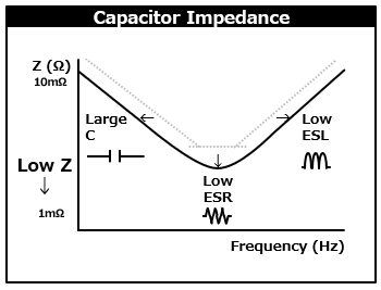
By improving a capacitor toward larger capacitance, lower ESR, and lower ESL through the methods shown below, impedance can be reduced in the respective frequency ranges.
| Low Z |
|
For processors that generate large load transients, the impedance requirement is often several mΩ or less, and in high-end applications it is the sub-1 mΩ range. However, available capacitors are generally in the range of several tens of milliohms to several milliohms, and capacitors below 1 mΩ do not exist as single components. Therefore, the required low impedance is achieved by using multiple capacitors in parallel.
Another point requiring attention is the capacitor frequency coverage. Processors require low impedance over a wide frequency range from the kHz band to the MHz band*. This is because a processor load transient consists of such broad frequency current components. However, the frequency range in which a single rating capacitor can provide low impedance is limited. For this reason, capacitors with different capacitance ratings and sizes are combined to cover the entire required frequency range. In general, combinations of capacitors from several hundred uF to several hundred nF are used. By satisfying the low-impedance requirement across the required frequency range with such capacitor combinations, voltage fluctuation can be kept within the allowable range.
- * Low impedance is required in even higher-frequency range, but this is addressed by capacitors in the processor package.
In addition to using capacitors, expanding the power supply low-impedance region into higher frequency range is also considered for suppressing voltage fluctuation. In other words, it is improvement of power supply response*, which was also mentioned in the explanation of inductors. This means that current can be supplied more quickly from the inductor, allowing voltage fluctuation to be suppressed even with a smaller number of capacitors. Improved power supply response is achieved by reducing delays in the feedback control and inductor current slope. Increasing the switching frequency is one common method for achieving this. Higher switching frequency reduces the feedback control delay, and allows use of low-L inductors with steep current slopes while keeping ripple current within the allowable range. Power supply response can also be improved through the circuit topology improvement and control circuit adjustment.
- * This is also referred as the power-supply bandwidth frequency (FBW) or the crossover frequency (Fcrossover).
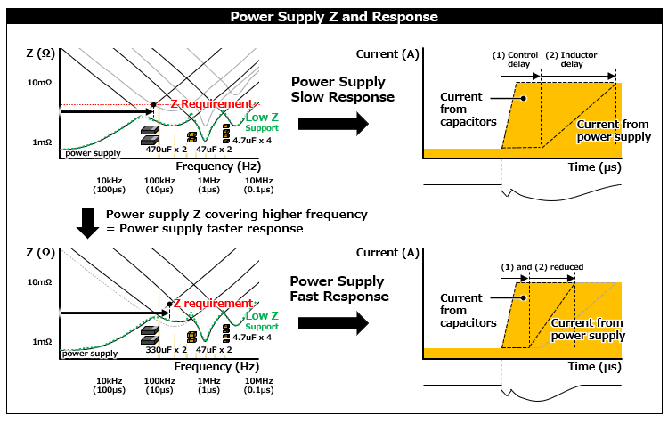
In reality, however, there are limits to improving power supply response. Increasing the switching frequency worsens power supply efficiency, and excessive tuning of the power supply topology or control circuit toward the response performance can impair control stability. Since the power supply response is adjusted only within a range that does not sacrifice the efficiency or stability required by the target application, the appropriate use of inductors and capacitors remains important.
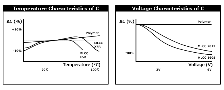
As described above, capacitors play a particularly important role in ensuring stability. However, as with inductors, depending on the type and product, capacitors’ characteristics may change significantly under certain conditions. It is important to check characteristic changes under operating conditions such as voltage and temperature, and to select capacitors with sufficient margin.
3. Summary of the Four-Part Series
In the first two parts, we explained processors, and in the latter two parts, we explained power supplies for processors followed by inductor and capacitor contributions.
Panasonic Industry offers a broad lineup of capacitors and inductors suitable for processor power supply applications. We support the design and development efforts of processor, power IC, and electronics manufacturers by providing reliable and high-performance components. When designing processor-based systems, we encourage you to explore Panasonic Industry's component solutions.
Finally, the key points of the four parts are summarized below.
- ①Processors have achieved higher performance mainly through circuit miniaturization resulting in increased circuit scale, supporting the evolution of the information society.
They continue to attract attention as key components that will support further social development driven by AI, high-speed communications, and related technologies.
↓ - ②Different types of processors are used appropriately according to application needs, based on versatility and performance balance.
Depending on requirements for size and performance efficiency, co-processors may be integrated into a single package.
↓ - ③Every processor requires power supplies to operate. There are several solution types for power supply designs, which are selected according to requirements.
For processor power supplies with large load current and low operating voltage, reducing power loss, or achieving high efficiency, and suppressing voltage fluctuation, or achieving high stability, are especially important.
↓ - ④Inductors and capacitors play important roles in the operation of processor power supplies.
Inductors continuously supply current, and their low DCR is especially important characteristic to reduce power loss.
Capacitors instantaneously supply or absorb current, and their low impedance is especially important characteristic to suppress voltage fluctuation occurring at instantaneous current transients.
| Processor |  |
Power Supply / Components | ||||
|---|---|---|---|---|---|---|
| Requirement | Solution | Requirement | Solution | |||
| Higher performance |
Lower voltage Higher current |
Need to reduce power loss Especially P = I2 x R |
Especially low DCR in inductors | |||
| Need to suppress voltage fluctuation Especially ΔV = ΔI x Z |
Especially low Z in capacitors | |||||
4. Related product information
5. Related Articles
- Processor Basics (1) - Overview and Trends -
- Processor Basics (2) - Types and Usage -
- Processor Basics (3) - Overview and Design of Power Supplies -
- Will Generative AI Drastically Change the World? - The Evolution required for AI Services and the capacitors Supporting Them - (First Part)
- Will Generative AI Drastically Change the World? - The Evolution Required for AI Services and the Capacitors Supporting Them - (Second Part)
6. Tags Related to This Article
 Search by
 Search by
 Search by