Processor Basics (3): Overview and Design of Power Supplies
2026-10-28

In the previous article, we introduced the types and characteristics of processors and how they are used. In this article, we explain the power supplies that are essential for processor operation, including their overview and the design solution types used depending on the purpose.
1. verview of Power Supplies for Processors
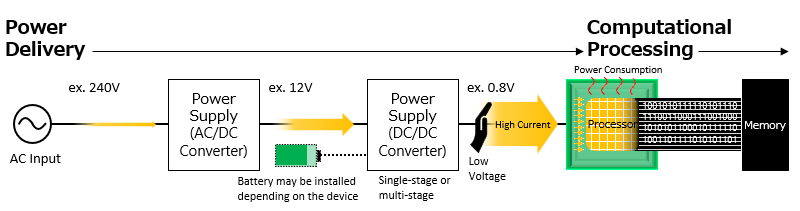
All electronic products require power to perform their workloads. Thus the power supply circuits are the essential part of the system. The processor, which performs the main calculations, requires a relatively large amount of power within the entire system. However, it is difficult to generate the low voltage and high current used by the processor directly from the AC power supply or battery, so it requires DC/DC converter insertions before reaching the processor. Inserted DC/DC converters can be a single stage or multiple stages depending on the other circuits, components, and applications. In this article, we will focus on the final stage DC/DC converter that delivers current directly to the processor as a power supply for the processor.
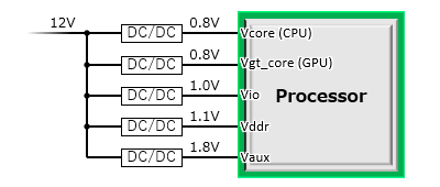
Another thing to be noted is that the processor does not receive power from the DC/DC converter just through a single path. The power paths are divided according to the function differences within the processor. Each path receives different optimal voltage and current for efficient operation. These paths are generally called voltage rails. Among these, the core rail is connected to the core circuit that performs the main calculations and requires a larger current than the other rails. Other voltage rails within the processor are different depending on the processor type or the architecture even within the same processor type. For example, in a certain SoC, in addition to the CPU and GPU core rails, there are also I/O, memory, and auxiliary function rails. The number of these voltage rails is generally increasing as processors become higher performance and feature-rich.
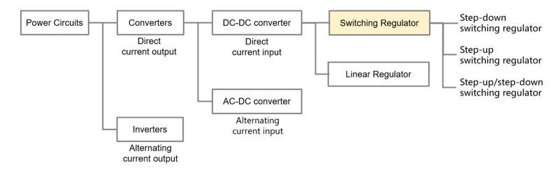
Now to understand DC/DC converters, let us first look at the basic classification of power supplies. Broadly speaking, operating methods can be divided into switching and linear types. Switching type is more efficient yet more complex. Linear type is less efficient yet less complex. Switching type is the one primarily used for processors. This is because making low heat generation and high efficiency are the crucial factors required by processors which use large currents. Still linear converters are sometimes used for fine voltage adjustments or low current rails of a processor where power efficiency is not a major concern.
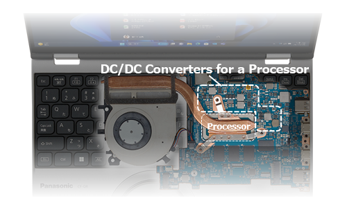
When pursuing high power efficiency, the placement (layout) of the DC/DC converters is also important. In most cases, high current DC/DC converters are placed near the processor, as in the example below. Since a large current is delivered from the DC/DC converters to the processor, placing the power supply far away causes long wiring between them, resulting in unnecessary power loss. DC/DC converters for processors are sometimes specifically referred to as VR (Voltage Regulator) or POL (Point of Load), and the latter term literally suggests that they should be located close to the processor
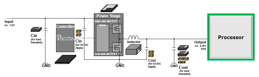
Next, let's look at the main components and configuration of a switching type DC/DC converter for a processor. Although there are various circuit methods, or topologies, this article focuses on the widely used buck type, which is the most widely used. The four main components are the controller, power stage, inductor, and capacitor. *Components related to control settings, such as resistors, will not be explained here.
By combining these, the high-voltage and low-current input is converted into the low-voltage and high-current output used by the processor. The controller and power stage looks may be confusing sometimes, but their roles are clearly different. The controller acts as the brain, detecting changes in the processor’s voltage and current requirements and issuing switching commands. The power stage acts as the muscle, switching according to those commands and performing power conversion.
| IC | Role | |
|---|---|---|
| Controller |  |
|
| Power Stage (DrMOS,SPS) |
 |
|
Including the operation of the inductor and capacitors, the power conversion process can be described as follows.
- Low-voltage conversion
Through monitoring fluctuations in the output voltage rail that supplies voltage and current to the processor, the controller alternately turns the high-side MOSFET and low-side MOSFET in the power stage ON and OFF. By shortening the ON time of the high-side MOSFET connected to the input voltage, the voltage is converted to the low voltage which is used by the processor.
- High-current conversion
The ON time of the high-side MOSFET is temporarily increased until the current reaches the high level required by the processor. At this time, current is supplied to the output while magnetic energy is stored in the inductor. When the high-side MOSFET is turned OFF, current supply from the input is interrupted, but the energy stored in the inductor is discharged, allowing a gradually decreasing current to continue flowing to the output. After that, a constant ON/OFF ratio corresponding to the required output voltage is repeated and maintains continuous current output at the high level.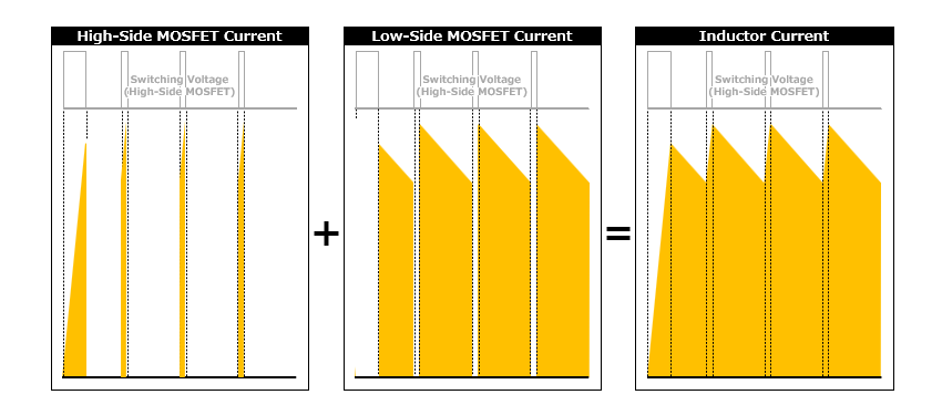
- Input/output current smoothing
Ripple current generated on the input and output sides of the DC/DC converter by MOSFET switching is smoothed by nearby input capacitors (Cin) and output capacitors (Cout), preventing ripple current from propagating to the circuits connected to the input and output. This is called decoupling.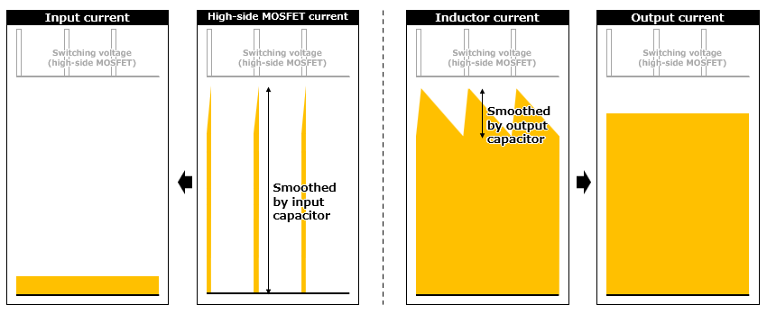
The above is the general power conversion operation of a DC/DC converter. However, in modern processors, fast and random high-current fluctuations, known as (dynamic) load transients, commonly occur according to changes in computational load. These occur in a lower frequency range than switching ripple current and are often the largest current fluctuation on the processor voltage rail. Therefore, in many cases, capacitors are added to the input and output of the DC/DC converter to respond to load transients.
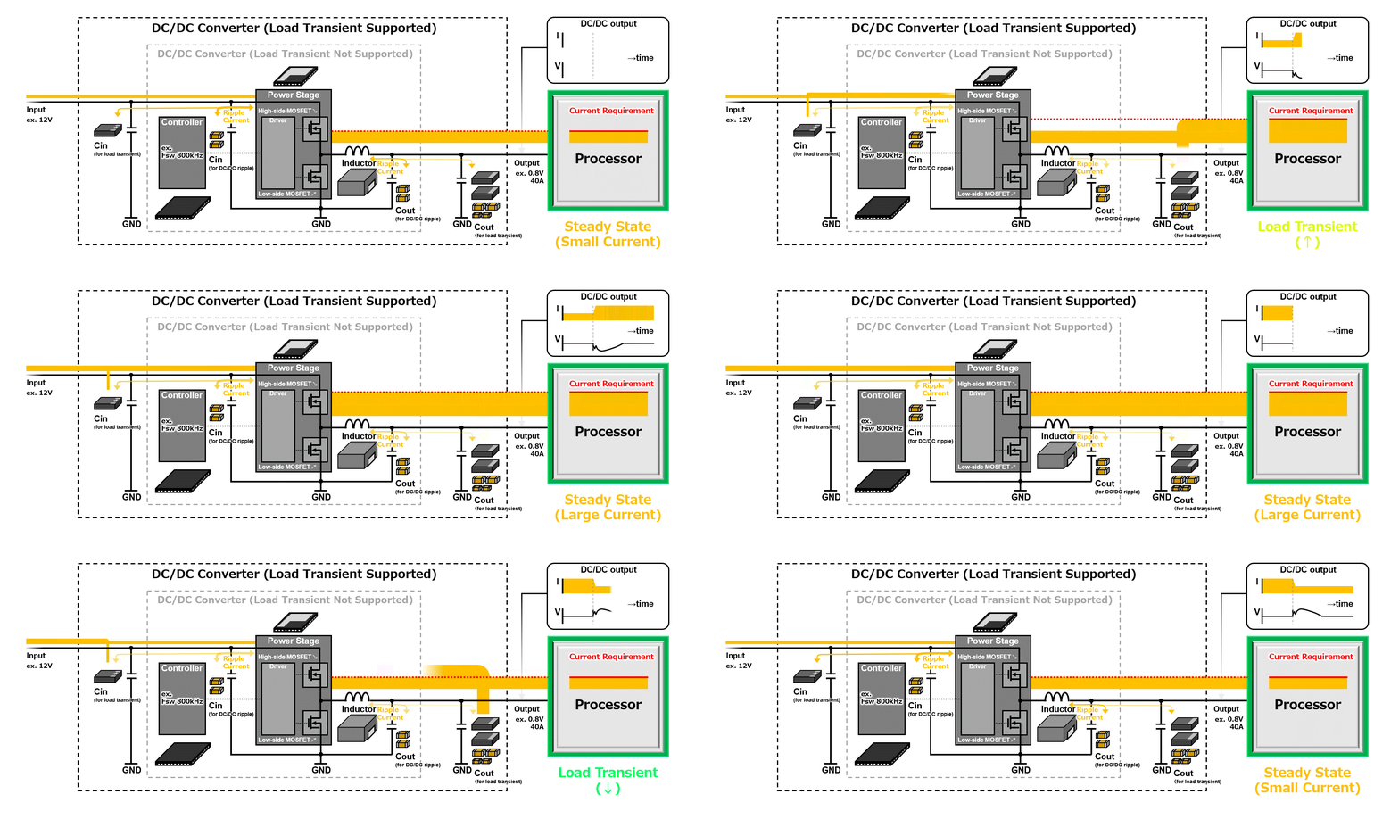
The required capacitors depend on the degree of load transients in the processor, but by adding sufficient capacitors for each case, the required current supply with stabilized voltage can be achieved. Without sufficient capacitors, the required current may not be supplied during the interval between when the processor requests a large current and when the DC/DC converter responds, that is, when the inductor begins supplying current. As a result, the voltage may drop significantly and could cause the processor to stop operating.
Processor power supplies are based on the components and operation described above, but actual electronic product designs involve various practical requirements, including circuit stability, power efficiency, size, cost, and lead time. Taking the degree of these requirements into account, the optimal power supply design for each product is narrowed down. For example, reducing a DC/DC converter size can generally be achieved by increasing the switching frequency and using smaller components. However, higher frequency operation involves a trade-off with high efficiency and, in some cases, may require special components, resulting in higher cost. Therefore, each factor is verified and the design is adjusted while considering the overall balance.
| Requirements | Solution Examples | ||
|---|---|---|---|
| High Stability and Reliability |  |
Designing for stable operation across a wide temperature range and long operating periods to prevent market failures. | Evaluate components and circuits under worst-case assumptions. Use components with proven reliability. |
| High Efficiency and Power Saving |  |
Designing to minimize power loss as much as possible in order to reduce operating power costs. | Use low-frequency switching and components with low loss. Use high-voltage power distribution and shorten the distance between the processor and the power supply. |
| Compact Size and Space Saving |  |
Designing the power supply as compact as possible in order to meet required product size and mounting-area constraints. | Use high-frequency switching and compact high-performance components. Use power ICs with a higher level of integration. |
| High Availability and Low Cost |  |
Securing flexible and stable designs and procurement sources to support business continuity and competitiveness. | Procure a large volume of power ICs and components. Create common designs that support multiple supplier sources and can be reused in multiple products. |
| Simplicity and Speed |  |
Completing the design easily with minimal design processes in order to shorten product development lead time. | Use reference designs provided by IC manufacturers. Use power ICs with a higher level of integration. |
Considerations to the requirements above are made at various stages of power supply design, but the overall direction is largely determined by the choice of power supply design types. Let us therefore look at the basic ones and their characteristics.
2. ower Supply Solution Types for Processors
2-1. Discrete Solution
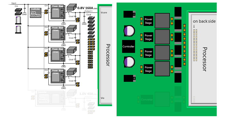
A discrete solution is the most common design type of DC/DC converters for a processor. The controller and power stage described above are implemented as separate discrete packages*1. This solution is often used because it enables flexible, low-cost design for high-current power supplies. By using multiple power stages in parallel, a discrete solution can support large currents. This is called multiphase design. For example, even if a single power stage can handle only up to 40 A of continuous current*2, using four in parallel, which is called four phases, allows 160 A of continuous current to be supplied to the processor.
- *1 In some cases, the power stage is further separated into MOSFETs and drivers in individual packages.
- *2 Some power stage products have maximum current ratings exceeding 100 A, but efficiency decreases near the maximum rating. Therefore, they are often used in a current range where high efficiency of over 90% can be maintained.
| Advantage | Low cost, multi-sourcing, high design options, flexible layout, and support for high current through multiphase design. |
| Disadvantage | Much design effort, and large size. |
| Suitable for | High-current rails with enough mounting area, Priority on flexibility and low cost. |
| Application examples | PCs, GPUs, servers, accelerators, PCs, network, industrial, automotive equipment, and other applications with high-current rails. |
<Circuit Diagram and Layout Image>
2-2. Converter Solution (Regulator Solution)
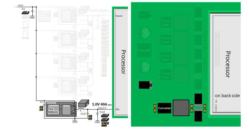
A converter solution, or regulator solution*3, integrates the controller and power stage into a single IC, making it smaller and simpler than a discrete solution. It is best suited for cases where the required current is up to several tens of amperes that can be handled by a single phase and where mounting area is limited.
- *3 The terms converter and regulator can be slightly confusing because in wider sense the terms DC/DC converter or switching regulator cover all design solution types. However, because a single power IC can function as a DC/DC converter, or switching regulator, this terminology is commonly used.
| Advantage | Smaller size, simpler design, and shorter design period. |
| Disadvantage | Usable current range limited up to several tens of amperes, and generally not suitable for multiphase uses. |
| Suitable for | Low-medium-current rails, Priority on design simplicity and usability. |
| Application examples | All types of applications, where voltage rails requiring currents from several amperes to several tens of amperes. |
<Circuit Diagram and Layout Image>
2-3. Module Solution
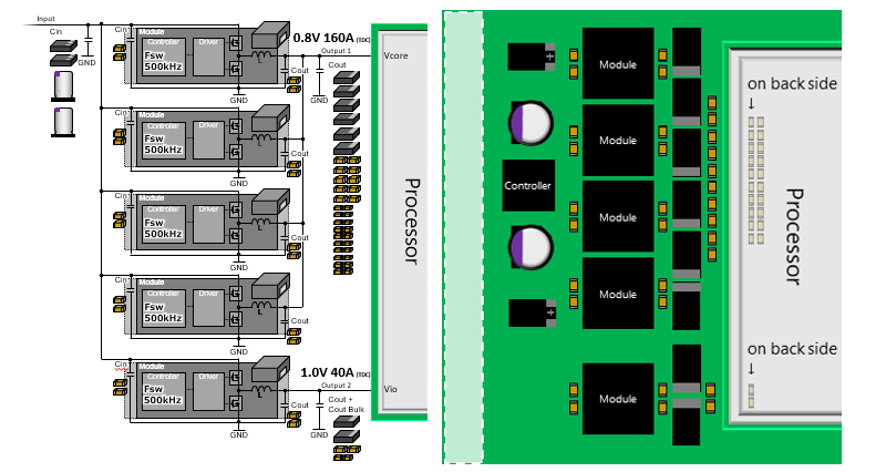
A module solution is a high-density design type in which the controller*4, power stage, inductor that occupies a large portion of the power supply area, and some capacitors*5 are integrated into a single package. In addition to being compact, it helps shorten the design period because fewer component-level evaluations are required.
- *4 In module products intended for multiphase uses, the controller is not integrated.
- *5 Although some capacitors may be integrated, external capacitors are generally added because the required capacitor values vary depending on the degree of load transient required by each processor.
| Advantage | Smaller size, simpler design, shorter design period, and support for high current through multiphase uses. |
| Disadvantage | Higher cost, and layout restrictions because of larger fixed dimensions. |
| Suitable for | High-current rails with limited mounting area, Priority on a short design period and easy design. |
| Application examples | High-end accelerators, network, industrial equipment, and other applications including high-current core rails and medium-current auxiliary rails. |
<Circuit Diagram and Layout Image>
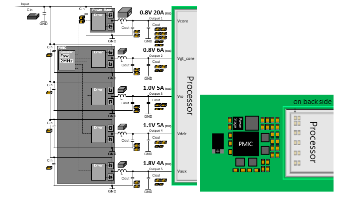
2-4. PMIC Solution
PMIC (Power Management IC)*6 is a power IC optimized for a specific processor or system. Within a single IC, it integrates a controller and power stages for the multiple rails, required by the target processor or system.*7
With a PMIC, power supply design can be completed using only one or a few power ICs, enabling simpler design and smaller size. On the other hand, PMICs are limited to specific supported processors or systems, and the current they can supply generally remains in a relatively low-current range. Therefore, for high-performance processors, some designs use a discrete solution for high-current core rails while using a PMIC solution to cover multiple other low-current rails.
- *6 PMICs are so named because they perform not only power conversion for multiple voltage rails but also management of startup and shutdown timing. PMICs also exist for systems other than processors, such as LCD panels and cameras. In some cases, products that perform only power management without power conversion are also called PMICs.
- *7 When the current value is large, PMICs may be used together with external power stages, but when the current is too large, a design solution other than a PMIC is generally selected.
| Advantage | Multiple voltage rails required by a specific processor are integrated, making this the most effective option for power supply miniaturization and design simplification. |
| Disadvantage | Target applications are limited to specific processors, and cost is high. |
| Suitable for | Certain SoCs with dedicated PMICs available, Priority on small area and less design effort. |
| Application examples | Smartphones, tablets, and laptop PCs, embedded equipment, and automotive IVI/ADAS applications. |
<Circuit Diagram and Layout Image>
As described above, power supply solution types for processors are used according to the specific design requirements and application conditions. Based on these solution approaches, power supply technologies continue to evolve and improve in order to meet the increasingly demanding requirements of processors.
In this article, we introduced the role of power supplies required for processors, their components, configuration, and operation, and the basic design solution types. Regardless of which design solution is selected, passive components such as inductors and capacitors are used and play a major role in achieving high-performance power supplies. In the next article, we will explain in detail the specifications of power supplies for processors and the characteristics required of inductors and capacitors in response to those specifications.
3. Related Articles
- Processor Basics (1) - Overview and Trends -
- Processor Basics (2) - Types and Usage -
- Processor Basics (4) - Key Characteristics Required for Inductors and Capacitors -
- Will Generative AI Drastically Change the World? - the Evolution required for AI Services and the capacitors Supporting Them - (First Part)
- Will Generative AI Drastically Change the World? -The Evolution Required for AI Services and the Capacitors Supporting Them - (Second Part)
4. Tags Related to This Article
 Search by Category
 Search by Keyword
 Search by Product