Role That Soft Resin-End-face Electrode Plays in Chip Resistor
- Suppress Solder Cracking Caused by Heat Cycle -
2024-12-20
- Role and usage of the chip resistor
- Required performance of the chip resistor and quality problems
- Solder cracking development mechanism
- 4. Extending the time, it takes to develop solder cracking by adopting the soft resin end-face electrode and its effects
- Summary
- Product information related to this article
- Related articles
- Tags linked to this article
A resistor in an electric circuit adjusts the current flow and controls voltage in the circuit. A chip resistor is a type of resistor that is soldered to a circuit board. A rectangular chip resistor, a Panasonic product, adopts the soft resin end-face electrode developed by Panasonic, as a countermeasure against solder cracking that occurs under the influence of thermal expansion/contraction.*1This technology, called “Soft Termination Technology”, features the enhanced flexibility of the end-face electrode, which reduces stress applied to a solder junction, thereby extending the time it takes to develop solder cracking. Hence the technology significantly improves the durability and reliability of the resistor.
Role and usage of the chip resistor
Role of the resistor
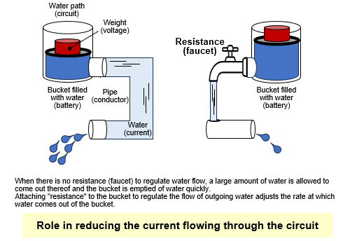
A resistor in an electric circuit adjusts the current flowing in the circuit. It reduces current or lowers voltage in the circuit. The resistor works just like a faucet controlling the amount of water coming out. It adjusts the amount of current, allowing the proper amount of current to flow.
Usage of the chip resistor
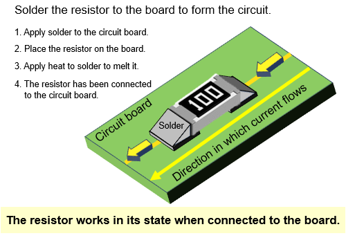
One generic method of connecting the chip resistor to a board is "soldering." Solder works like an adhesive. It firmly bonds the chip resistor to the board. The chip resistor is placed on a part where solder is applied, and then is exposed to heat, which melts the solder. As the solder cools and solidifies, the resistor is firmly fixed to the board and can carry a current flow. No resistor is used as a stand-alone element. It is always used as an element connected to the circuit board.
Required performance of the chip resistor and quality problems
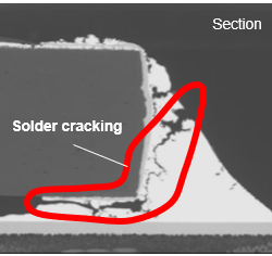
In general, the most important performance factor of a resistor is to keep its resistance stable for a long period under various environmental conditions. However, one of the most common failure mode that affect the resistor quality is the cracking of the solder junction caused by temperature changes. This problem is called "solder cracking." Once solder cracking occurs, the circuit may become incapable of functioning normally even if the resistor itself is not damaged at all. Dealing with this kind of quality problem is extremely important for ensuring the reliability of the resistor.
Solder cracking development mechanism
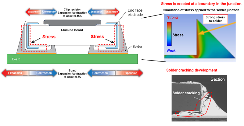
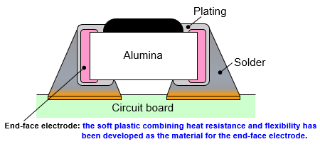
Solder cracking occurs because materials joined together have different CTE (Coefficient of Thermal Expansion). For example, in the case of the chip resistor, an alumina substrate (which makes up the chip resistor) with a small thermal expansion coefficient (equal to ~7.6 ppm/K) and a printed board with a large thermal expansion coefficient (about 15 ppm/K for FR4 PCB) are soldered together. In such a case where materials with different CTE are joined together, repeated cycles of expansion and contraction of the materials caused by temperature changes create irregular stresses at the junction. As a result, repetitive loads are applied to the solder junction, which causes solder cracking.
Extending the time, it takes to develop solder cracking by adopting the soft resin end-face electrode and its effects
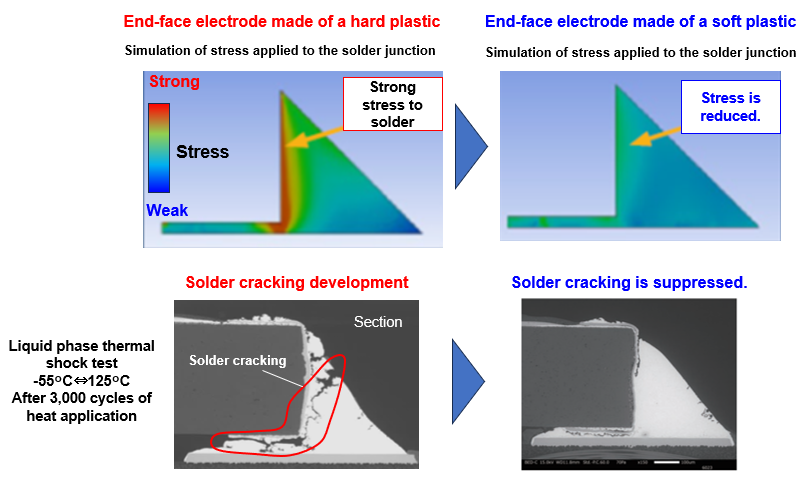
The soft resin end-face electrode developed by Panasonic (Soft termination technology) extends the time it takes to develop solder cracking under temperature cycles. In this technology, the end-face electrode with enhanced flexibility exerts a cushioning function, thus reducing the stress applied to the solder junction.
Usually, there is a tradeoff between flexibility and heat resistance of the end-face electrode. Higher heat resistance leads to a harder material property, in which case solder cracking readily occurs. Giving priority to higher flexibility, on the other hand, results in lower adhesion, that is, solder separating easily from the chip. Panasonic, however, has succeeded in giving the soft resin end-face electrode both advantages: higher flexibility and higher heat resistance. The advantageous effects have been verified in comparison tests conducted on various types of end-face electrodes under temperature cycles.
In the tests, the rate of occurrence of an open circuit failure (the circuit is opened because of wire-breaking) under cycles of low-temperature and high-temperature conditions was measured. The test results demonstrate that, when subjected to temperature cycles, soft resin end-face electrode has a longer cycle compared to metal film electrode (sputtered film electrode) or hard resin end-face electrode, and slows down the rate of occurrence of open circuit failure. This technology thus significantly improves the connection reliability of the resistor, allowing it to maintain stable performance over a long period.
| End-face electrode | Soft plastic | Hard plastic | Sputtered electrode |
| Material hardness | Soft | Hard | Very hard (metal) |
| Heat resistance | High | High | High |
| Effect of reduction in stress to the solder junction |
High | Low | No |
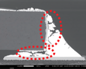
| Liquid phase thermal shock test -55°C⇔125°C after 3,000 cycles of heat application |
 |
 |
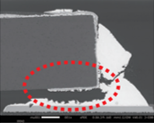 |
| No crack | Crack development | Crack development |
Soft termination technology is used in every thick film chip resistor manufactured by Panasonic, with case size higher than 0201, making our components robust and reliable, even in harsh temperature conditions.
Summary
Panasonic's rectangular chip resistor suppresses solder cracking by using a soft resin end-face electrode.*1This technology enhances the flexibility of the end-face electrode and reduces stress to the junction, thus slowing down the solder cracking development process. As a result, the resistor offers improved durability and reliability, maintaining its stable performance over a long period.
*1 If you want to know more about products adopting the soft resin end-face electrode, access the inquiry form on our web page or contact our customer counter.
Product information related to this article
Related articles
Tags linked to this article

