Basic Knowledge of Resistors
-Roles, Units and Symbols, Standards-
2018-04-16
- Roles of Resistors
- Principles of Resistors
- Technical Terms Related to Resistors
- Standards Related to the Indication of Resistance Values and Resistance Tolerances
- Structure of Resistors
- Selecting Resistors
- [Selection based on Mounting Methods]Whether it is surface mount or lead insertion/fixed mounting
- [Selection based on Performance, Characteristics, and Size Requirements]Ratings, accuracy, temperature characteristics, functions, environmental resistance, heat dissipation, size, height, etc.
- [Selection of Chip Resistors]
- Related product information
- Tags related to this article
Resistors are one of the most basic components, together with capacitors and inductors, and are ubiquitous in electric/electronic equipment. Because resistors are so common, people working with electricity may tend to neglect them. However, resistors are so important that electric/electronic circuits would not be viable without them.
Roles of Resistors
Resistors are passive components with a specific electric resistance.
The work of a resistor is based on Ohm's law, i.e., voltage (V) = current (I) × resistance (R).
Resistors have four main roles: current control, voltage division, current detection, and biasing.
[Current Control]
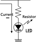
A resistor is able to control current in an electronic circuit to the rating or lower. For example, in an LED circuit, a resistor is connected in series with an LED to suppress the current to the rating or lower, thereby preventing the LED's burnout.
[Voltage Division (dividing a voltage)]
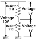
Connecting two or more resistors in series will enable the dividing of a voltage into voltages that are proportional to the resistance values connected.
[Current Detection]
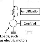
When current flows through a resistor, a voltage converted from the current is generated at both ends of the resistor.
The current flowing through the circuit can be calculated by measuring this voltage.
[Biasing]
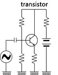
Providing a voltage for operating a semiconductor component such as a transistor is referred to as "biasing."
Biasing requires the application of different voltages to the terminals (emitter, collector, and base) of a transistor.
Resistors are also used as dumping resistances, terminators, pull-up/pull-down resistors, etc.
Principles of Resistors
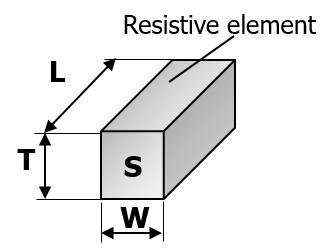
A resistance value is determined by the resistive element material's resistivity, cross-sectional area, and length.
R =
ρ・L
S
- R
- Resistance value(Ω)
- L
- Length(㎝)
- W
- Widt(㎝)
- T
- Height/thickness(㎝)
- S
- Cross-sectional area(W・T)
- ρ
- Resistivity(Ω・㎝)
As indicated by the equation, the resistance value is obtained by multiplying the resistivity ρ(Ω・cm) by the length L of the resistive element and dividing it by the cross-sectional area S. Some metal resistivity values are shown for reference purposes.
| Metal name | Symbol | Resistivity (μΩ・cm) |
|---|---|---|
| Gold | Au | 2.40 |
| Silver | Ag | 1.62 |
| Palladium | Pd | 10.8 |
| Nickel | Ni | 7.24 |
Technical Terms Related to Resistors
There are several parameters for resistors' specifications and ratings. Related technical terms are listed below. The four entries in bold represent resistors' basic parameters.
| Rated power (W) | The maximum power value that can be continuousy applied at the rated temperature |
| Resistance value (Ω) | The magnitude of electric resistance. Resistance values are standardized in official standards. |
| Resistance tolerance (%) | The upper and lower limits of allowable resistance values. It indicates the accuracy of resistance values. |
| Temperature coefficient of resistance (TCR)(×10-6/K) | Resistance values' rate of change with respect to changes in the ambient temperature |
| Limiting element voltage (maximum operating voltage) (V) | The maximum voltage that can be continuously applied |
| Category temperature range (°C) | The range of ambient temperature at which the resistor can be continuously used |
| DC resistance value (Ω) | The reference resistance value that is measured when a DC voltage is applied |
| Dielectric withstanding voltage(V) | The maximum voltage applied to the exterior of product insulation, agast which the insulation can be ensured |
| Insulation resistance (Ω) | The minimum resistance of the exterior of product insulation |
| Solder heat resistance | Electric and mechanical stability when immersed in solder |
| Moisture resistance | Electric and mechanical stability against moisture |
| Temperature cycle | Electric and mechanical stability against temperature changes |
| Durability (Load) | Electric and mechanical stability when the rated voltage is continuously applied at the rated temperature |
| Terminal strength | Mechanical strength when a mechanical load is applied to the terminal section |
| Vibration resistance | Electric and mechanical stability against vibration |
| Flame retardance | Self-extinguishing and non-flammable properties when overloaded |
Standards Related to the Indication of Resistance Values and Resistance Tolerances
As stated for the technical term "resistance value," the indication of resistance values and tolerances is based on standards and conforms to the following.
- IEC 60062:Marking codes for resistors and capacitors
- IEC 60063:Preferred number series for resistors and capacitors
Resistance values are arranged into a series of standard values based on the above standards. Resistance values do not consist of integers such as 1 Ω, 2 Ω, 3 Ω, but are odd values such as 2.2 Ω and 4.7 Ω. This is because resistance values conform to standard numbers (E series). The "E" in E series stands for "Exponent," and the appended number, for example, 24, is a divisor. In other words, E24 indicates 1 to 10 divided by a geometric series (24th root of 10). Because resistors are often used based on ratios and proportions, these serialized values tend to be easier to use than integers.
| Series | Estimated resistance tolerances | Common ratio | Resistance value(An example) |
|---|---|---|---|
| E12 | ±10% | 12 10≈1.21 | 1.0, 1.2, 1.5, 1.8, 2.2, 2.7, 3.3, ・・・ |
| E24 | ±5% | 24 10≈1.10 | 1.0, 1.1, 1.2, 1.3, 1.5, 1.6, 1.8, ・・・ |
| E96 | ±1% | 96 10≈1.02 | 1.00, 1.02, 1.05, 1.07, 1.10. ・・・・ |
Structure of Resistors
The basic structures of typical resistors are shown below. Although they are used in accordance with applications, chip resistors have been mainly used in small equipment in recent years.
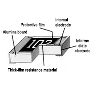
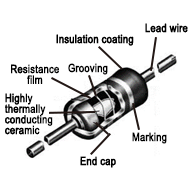
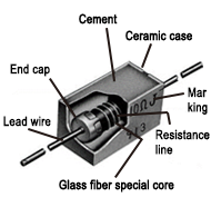
Selecting Resistors
The selection of resistors during the design phase must meet complex requirements such as size, circuit board mounting methods, and performance.
[Selection based on Mounting Methods]
Whether it is surface mount or lead insertion/fixed mounting
Although surface mount has been more common in recent years, it is necessary to select lead-insertion or screw-fixing resistors depending on the circuit scale and specifications. Ideally, one mounting method is determined for one type of board based on the examination of the entire circuit board's mounting specifications.
| Mounting methods | Resistors | Examination of packing/board mounting | Examination of soldering/installation |
|---|---|---|---|
| Surface mount | Chp resistors Chip resistor networks, etc. |
Low power resistors (carbon/metal film, etc.) | Reflow Flow |
| Lead insertion /fixing |
Low power resistors (carbon/metal film, etc.) Power-type resistors (windings, etc.) Lead terminal fixed network resistance, etc. |
Whether or not automatic mounting is possible (radial/axial taping, etc.) Lead processing for manual installation |
Flow Manual installation Screw fixing |
[Selection based on Performance, Characteristics, and Size Requirements]
Ratings, accuracy, temperature characteristics, functions, environmental resistance, heat dissipation, size, height, etc.
In addition to mounting methods, there are requirements related to the performance, characteristics, and sizes of individual resistors. In order to meet individual requirements, the desired type (i.e., surface mount resistors) may not be used. There may also be trade-offs such as greater restrictions and fewer choices in exchange for compatibility with harsh environmental conditions. Selecting resistors requires an examination from an overall perspective including performance, characteristics, sizes, and mounting methods.
[Selection of Chip Resistors]
Although the selection of chip resistors needs to meet specific requirements such as performance and characteristics, it is usually efficient to select them by following the steps shown below.
- 1) Select single or composite chip resistors.
- 2-1) For single chip resistors, select thick-film or thin-film chip resistors.
- 2-2) For composite chip resistors, select chip resistor arrays (independent circuits) or chip resistor networks (parallel circuits).
- 3) Select the shape of resistors in accordance with the use voltage (power).
- 4) When there are overlapping types, select based on other performance criteria.


