The flow of steps and points to note for selecting a Micro Chip Fuse suitable for given service conditions is shown here.
Flow of steps for selecting a fuse
- Check the shape/size of the fuse, rated voltage, interrupting rating, and safety standards.
-
Fusing current under abnormal conditions:
Determine the fusing current to be 200% or more the rated current. -
Normal current under normal conditions:
Determine the normal current to be 56% or less the rated current.
(It is recommended that the fuse be able to withstand a normal current flow for 100,000 hours or longer.) -
Inrush current under normal conditions:
Select a rated current value with a pulse withstand curve greater than 100,000 based on the inrush current waveform. - Check the fusing characteristics of an actual fuse
- Micro Chip Fuse selection tool
-
The tool allows you to select the product number of the Micro Chip Fuse you are looking for by simply entering the service conditions.

Selection point
Check the shape/size of the fuse, rated voltage, interrupting rating, and safety standards.
Select fuse specifications other than those for the rated current application according to the condition of the circuit to be used.
-
- ・Shape:
- Select the shape of the fuse by taking the attachment space on the board into account.
-
- ・Rated voltage:
- A voltage across both ends of the fuse is negligible under normal conditions; however, the full circuit voltage is applied to the fuse when it melts.
-
- ・Interrupting
rating: -
An excessive fusing current under abnormal conditions may result in a fusing failure.
Confirm that the fusing current (maximum current) under abnormal conditions is equal to or smaller than the maximum breaking current of the fuse.
- ・Interrupting
-
- ・Safety
standards: -
When safety standards are required, choose a fuse conforming to such standards.
(Panasonic's Micro Chip Fuse has acquired the UL/CSA safety standard certificate.)
- ・Safety
Example of service conditions
-
- -Shape
- : 1005(0402) size or smaller
-
- -Circuit voltage
- : 20 V max
-
- -Maximum current
- : 5 A max
(Under abnormal conditions)
-
- -Safety standards
- : UL standards are required.
Fuse specifications
-Panasonic’s applicable products: ERBRD
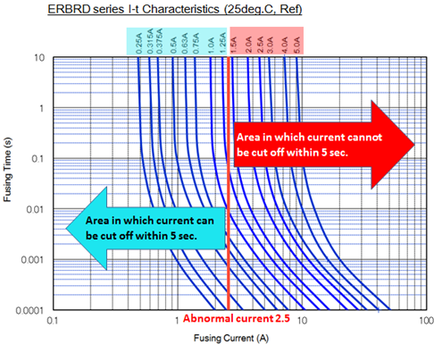
Fusing current under abnormal conditions
Select a rated current value based on the current (effective current value) that flows through the fuse under abnormal conditions and the fusing time of the fuse.
From an I-t characteristic graph, select a fuse that can cut off an abnormal current within a given fusing time and is activated by a current equal to or smaller than the rated current.
Example of service conditions
-
- -Effective current
(Under abnormal conditions ) - : 2.5A rms
- -Effective current
-
- -Fusing time
- : within 5 sec.
Fuse specifications
-Recommended rated current value:
1.25 A or less
Recommended rated current value (MAX)=2.5 A/200%
Current flow under normal conditions
Select a rated current value based on the current (effective current value) that flows steadily under a normal operating condition and current-passing time (life).
Determine the load factor from the current-passing time estimation graph and select the rated current fuse by taking the load factor into consideration.
Recommended rated current value (min.)
= current under a normal condition/load factor
Example of service conditions
-
- -Effective current : 0.5 A rms
- (Under normal conditions)
-
- -Energization time: 100,000 h
Fuse specifications
-Recommended rated current value:
1.0 A or larger
(Estimated load factor of 56% or lower for the passing of current for 100,000 h or longer)
Recommended rated current value ( Min ) =0.5A/56%
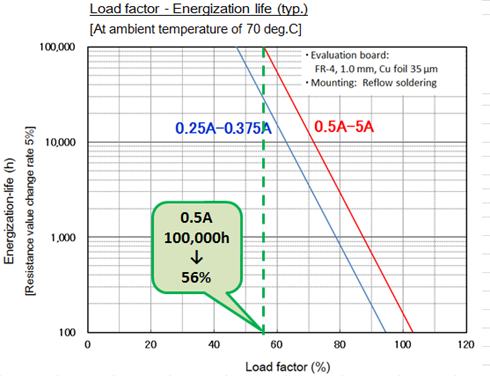
※Load factor=steady current/rated current
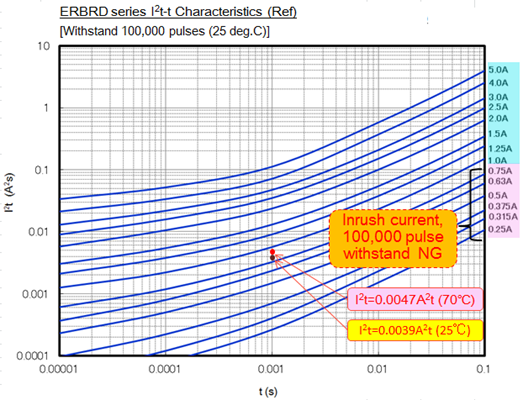
Inrush current under normal conditions
Select a rated current value, based on an inrush current that is generated upon switching the power supply on and off.
An inrush current larger than a steady current flows through the circuit when the power supply is switched on and off.
A fuse that does not fusing after being subjected to such an inrush current should be selected.
I2t is calculated from the current waveform, and the fuse is selected based on the 100,000 pulse withstand curve of an I2t-t characteristic curve.
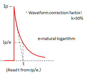
Example of service conditions
-
- -Peak current
- : Ip=2.8 A
-
- -Current duration
- : t=1 ms
-
- -Number of pulse
- : 100,000
Fuse specifications
-Recommended rated current value:
1.0 A or larger
-
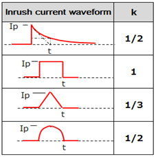
- I2t = Ip2×t×k
- = 0.0039 A2s (at 25°C )
-
- = 0.0047 A2s (at 70°C)
* The calculation is made with a 120% correction factor at 70°C.
From the result of (2)(3) (4), a recommended rated current under the above service conditions is determined to be 1.0 A to 1.25 A.
Check the fusing characteristics of an actual fuse
In reality, a selected product does not always exhibit the expected fusing characteristics because of a difference in heat conduction by the board or unexpected noise.
It is therefore imperative that at the final stage of fuse selection, the circuit should be operated with the fuse mounted on an actual circuit board and it should be confirmed that the fuse exhibits its expected fusing characteristics.
※If you have a problem with chip fuse selection, then please contact us.