Common Mode Noise of High-Speed Differential Data Transmission and Management of Internal Interference to Wireless communications
2018-03-05
Data communications that support the rapid progress of digital network devices in recent years have been speeding up due to increased data amounts, and are now being used by more mobile and miniaturized devices. As a result, noise inside final devices is getting more complex, and various noise management methods are under examination.
Normal Noise and Common Mode Noise
Noise is broadly classified into conduction noise and radiation noise. Conduction noise is further classified into normal mode noise and common mode noise depending on how it is transmitted.
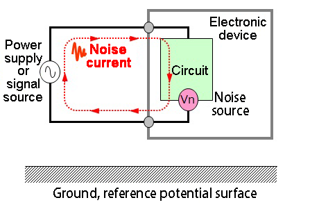

The noise current of normal mode noise makes a loop by passing through power supply or signal source lines to reach electronic circuits then returns to the power supply or signal source through the ground line of the circuit. The directions of the forward and return noise currents are opposite. Attempts to reduce radiation noise due to normal mode noise current are made through reducing the loop area of the noise current, inserting capacitors, inductors, or LC filters.
Common mode noise refers to noise whose current flows out through parasitic capacitance, etc., and similarly returns through parasitic capacitance, etc., via the ground plane, etc., of electronic devices. It is referred to as common mode (In-phase) noise because the direction of current noise is the same for both the power supply or signal source line side (Positive) and the ground line side of the circuit (Negative). Because common mode noise makes a large noise current loop through the ground plane, etc., small noise current may cause large noise radiation.
Digital data communications (Wired) in recent years including USB and HDMI are very fast, and many of them adopt the differential transmission mode. This is because transmission using two signals of the same amplitude in reverse phase reduces normal mode radiation noise, and when in-phase (Common mode) noise superimposes with data communication lines, the reception side cancels it out by receiving the difference. This method is less affected by external noise and ground and thus suitable for high-speed data transmission.
However, common mode noise may still occur in differential transmission with these advantages, thereby making it very important now to manage common mode noise in differential transmission.
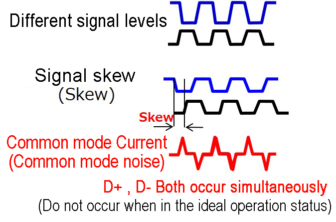
For example, as shown in the diagram on the right, even with differential digital data signals, common mode noise occurs due to an imbalance between the signals, such as different signal levels or signal skew. Besides, the frequency component of the common mode noise and that of the differential digital data signal are almost the same band and cannot be filtered by conventional LC filters, which are frequency separation type filters. In such cases, common mode noise filters are useful.
| Types of noise | Characteristics | Management measures |
|---|---|---|
| Normal mode | The same path with the power supply/signal source; the directions of the forward and return noise currents are opposite. | Capacitor,Ferrite beads,LCfilter |
| Common mode | The direction of the noise current is the same for both forward and return paths; the noise current is transmitted through the ground, etc., and makes a large noise current loop. | Common Mode Noise Filters |
What Are Common Mode Noise Filters?
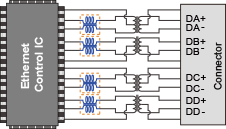
A common mode noise filter has two magnetically coupled coils, one of which is connected to D+ and the other to D- in differential transmission lines. The basic function of the filter is to pass differential signals and reject (suppress) common mode noise. The filter also reduces differential signal skew, thereby suppressing the occurrence of common mode noise.
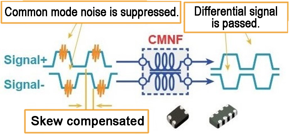
The diagram below shows how a common mode noise filter works on how to suppress common mode noise when a differential signal and common mode noise enter.
| Schematic diagram | Signal /noise | Effect (cross sections of coils) | Equivalent function |
|---|---|---|---|

Magnetic coupling between D+ and D- |
Differential (Differential digital signal) |

Magnetic fluxes are cancelled out, and the impedance is low. |

Transmission line |
| In-phase (Common mode noise) |

Magnetic fluxes are cancelled out, and the impedance is low. |

inductor |
When a differential signal enters, the flux generated by the D+ signal and that by the D- signal in the magnetically coupled circuit cancel each other out: therefore, no impedance is generated. When a common mode noise enters, the flux generated by the D+ signal and that by the D- signal enhance each other, generating high impedance. In other words, common mode noise filters serve as transmission lines for differential mode signals, and as inductors for common mode noise, blocking the passage of common mode noise. As in the description above, the structure of magnetic coupling between the coils of the D+ and D- transmission lines enables the separation of differential signals from common mode noise.
Common mode noise filters also reduce differential signal skew and suppress common mode noise. In common mode noise filters, a pair of coils are magnetically coupled and acts to cancel the changes of internal magnetic fluxes. The diagram on the right is an equivalent figure that shows the magnetic coupling state of a pair of coils inside a common mode noise filter. As shown in this diagram, when a change occurs in a magnetic flux because of a rising part to the signal due to skew, an inductive electromotive force that cancels it is induced on another coil, thereby reducing the skew and suppressing common mode noise.

Application Examples of Common Mode Noise Filters
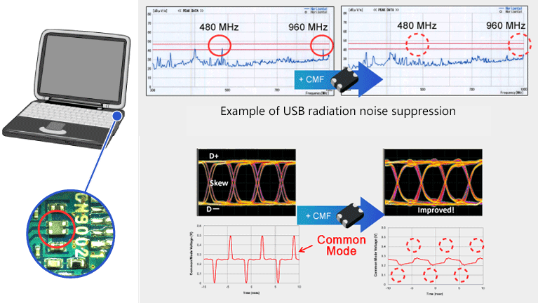
Here are some application examples of common mode noise filters. The diagram below shows the effect of suppressing radiation noise of a USB 2.0 interface. It indicates that the harmonic noise was suppressed by using a common mode noise filter. The diagram on the left shows D+ and D- data when there is skew with a differential digital signal. It shows that common mode noise has actually occurred. You can see that passing this through a common mode noise filter reduces skew and also suppresses common mode noise.
The above is an application example of USB. Common mode noise filters are also used for various types of high-speed differential data transmission adopted by a variety of devices such as PCs, displays, digital cameras, and smartphones.
-
LVDS/MIPI/V-by-One/eDP

-
HDMI

-
LAN(100/1000Base-T)
Management of Internal Interference with Wi-Fi
Noise from digital signal lines inside devices interferes with wireless communications.
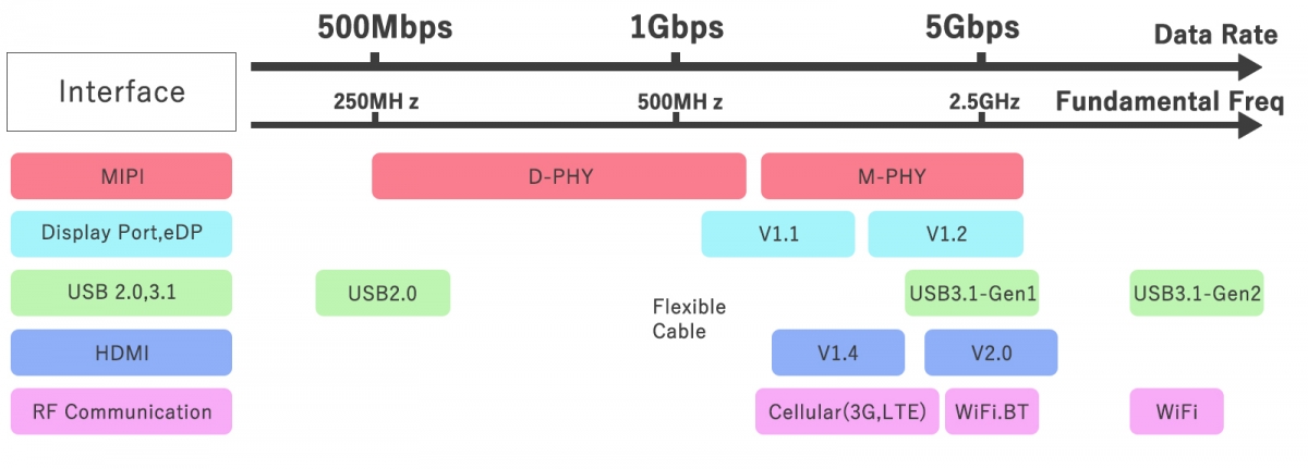
Mobile terminals, such as smartphones and tablets, have digital signal lines, such as USB and MIPI for camera and LCD control. Their narrow housings are also equipped with cellular, Wi-Fi, Bluetooth, GPS, and other wireless communication functions. As shown in the diagram below, nowadays transmission frequency bands of digital differential data communications are overlapping those of wireless communications. In particular, Wi-Fi wireless communication (Wireless LAN) of the 2.4 GHz band, which is a relatively low frequency band, is susceptible to noise effects. It is also an ISM band used for microwave ovens, etc., and is likely to be very crowded with interference. This causes noise from digital signal lines inside devices to enter antennas for wireless communications, decreasing their receiving sensitivity, which is becoming a problem.
IoT devices also require internal interference management.
The same can be said with IoT devices whose applications are increasing in a variety of fields in recent years. In particular, multi-devices equipped with a display, camera, USB, etc., require attention to interference from the 2.4 GHz band Wi-Fi, just like smartphones and tablets.
Against this backdrop, a wide range of IoT devices, in addition to smartphones and tablets, now use common mode noise filters as one way to manage internal interference by noise from digital signal lines inside devices.

Typical examples of wireless functions and interfaces equipped on IoT devices
- Wireless LAN (Wi-Fi) : Wireless communication
- USB : External data, charging function
- Displays, cameras, MIPI, DisplayPort(DP.eDP) : monitors, sensing, etc.
Example of improving receiving sensitivity using common mode noise filters
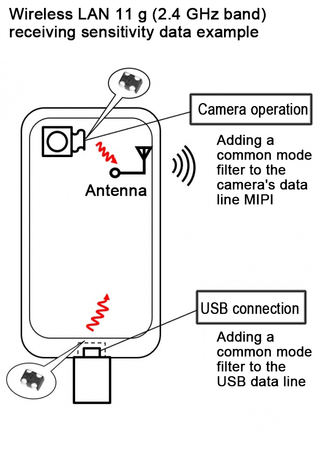
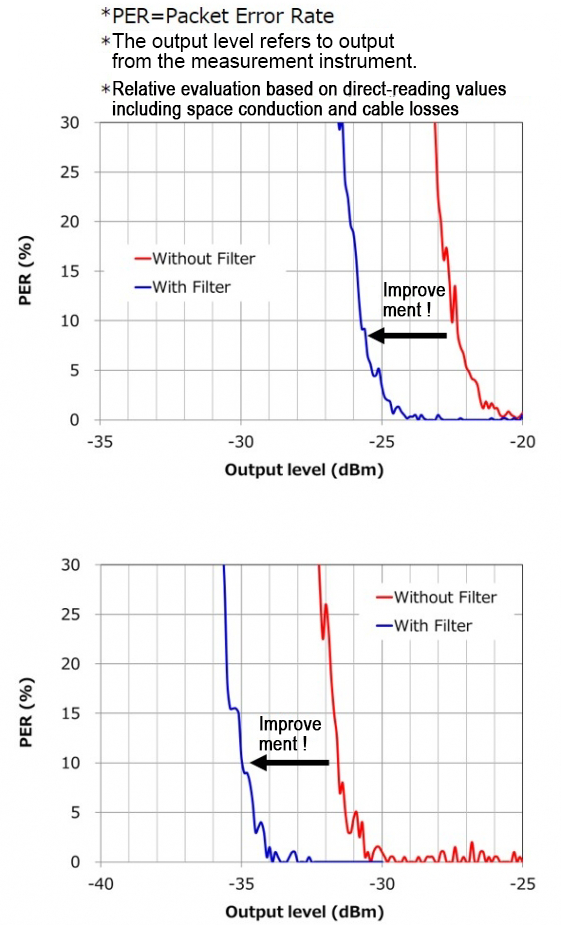
This data has been obtained by measuring the receiving sensitivity of Wi-Fi (Wireless LAN 11 g) of smartphones in a shield box using a receiving sensitivity measurement instrument. The graph shows the receiving sensitivities of a camera MIPI data line and a USB data line with/without a common mode noise filter. The red traces are without a filter, whereas the blue traces are with. The receiving sensitivities are relatively compared based on the relationship of the transmission power of the transmitter (Measurement instrument) received by the smartphones and error rates. Both indicate improvements that enable the reception of an electromagnetic wave lower by approx. 5 dBm.
Although this is an experiment using smartphones, these results also indicate that it is effective to insert a common mode noise filter in the high-speed differential data transmission lines of devices that perform high-speed differential data transmission and IoT devices with a mixed 2.4 GHz band Wi-Fi wireless communications.
Characteristics of actual common mode noise filters
When used for such applications, in order to suppress noise occurrence that enters the corresponding wireless communication band, the noise attenuation characteristics (Frequency characteristics) of common mode noise filters need to cover the wireless frequency bands. The table below shows the part numbers and typical characteristic charts of small common mode noise filters for IoT devices in recent years.
| Series P/N for MIPI,USB |
Size (mm) |
Features | Filter frequency characteristics |
|---|---|---|---|
EXC14CT |
0806 | ■Scc21 large attenuation -10dB@0.3~4.5GHz -20dB@1.2, 1.6GHz * Numerical examples are of EXC14CT500. |
Typical example EXC14CT500U |
EXC14CH |
0806 | ■Sdd21 low loss ■ Low AC resistance ■Scc21 broadband attenuation -10dB@0.55-5GHz typ. * Numerical examples are of EXC14CH350U |
Typical example EXC14CH350U |
|
EXCX4CH |
0605 | ||
EXCX4CZ |
0605 | ■Sdd21 low loss ■Scc21 large attenuation -30dBtyp.@2.4GHz * Numerical examples are of EXCX4CZ200X |
Typical example EXCX4CZ200X |


The blue traces of the filter frequency characteristics indicate the insertion losses of differential signals. Therefore, ideally they should be 0 dB. The red traces indicate the insertion losses (Attenuation) of common mode noise. Make selections by examining the band covered (Broad/narrow) and attenuation characteristics (Amount of attenuation).
Summary
Internal interference by common mode noise from high-speed differential data transmission lines entering antennas for wireless devices inside devices and decreasing their receiving sensitivity is becoming a problem. This problem also occurs with IoT devices. As an improvement measure, common mode noise filters are widely used for differential data transmission lines inside devices.
Related product information
Tags related to this article
This document summarizes the Noise measures related articles posted as technical information for the Optimal Solutions for Circuit Design.