Basic Knowledge of Inductors (2)
-Characteristics, Types-
2018-10-01
Basic Functions of Inductors
Inductors basically have the following functions.
- Generate a magnetic field when current flows through them. Conversely, current flows when their magnetic field changes.
- Convert electric energy to magnetic energy and store it.
- Pass DC but do not pass AC easily, and pass AC less easily at higher frequencies.
(1) and (2) are characteristics caused by the magnetic action of current and its reverse, i.e., electromagnetic induction. (3) refers to the DC and AC characteristics of inductors caused by impedance. The specific examples below show how these characteristics are used.
(1) Generate a magnetic field when current flows through them. Conversely, current flows when their magnetic field changes. ⇒ Principle of transformers
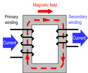
The structural example has two wound wires on the primary and secondary sides and therefore can be regarded the same as a transformer. Passing current to the primary-side wound wire will generate a magnetic field that will generate current on the secondary-side wound wire. This is due to electromagnetic induction, which is referred to as mutual induction in the case of transformers. Through this action, conversion to a desired voltage is possible based on the ratio of the number of turns between the primary- and secondary-side wound wires.
(2) Convert electric energy to magnetic energy and store it. ⇒ Principle of choke coils
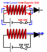
This is an example of an inductor in a DC/DC converter. Passing current through the inductor by turning the switch on will generate a magnetic field, causing the inductor to store energy in the form of magnetic energy. Stopping the flow of current through the inductor by turning the switch off will discharge the stored magnetic energy (the magnetic field changes), causing current to flow. This is also due to electromagnetic induction, which is referred to as self-induction in the case of inductors that consist of a single wound wire.
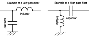
(3) Pass DC but do not pass AC easily, and pass AC less easily at higher frequencies. ⇒ Filter function
Inductors can be combined with capacitors to create low-pass, high-pass filters, etc. This makes use of their characteristic whereby the ease of passing AC is altered due to changes in impedance in accordance with frequencies. Impedance characteristics will be described later.
Characteristics of Inductors
Ideal and Actual Inductors (Impedance Characteristics)
Ideal inductors have no components other than inductance and suffer no energy losses. However, actual inductors possess resistance components (DC resistance: DCR) and capacitance (parasitic capacitance: Cp) in addition to inductance (see equivalent circuits). The resistance consists of the resistance components of a wound wire and a core. The capacitance mainly consists of the line capacity of a wound wire.
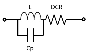
(Simplified equivalent circuits)
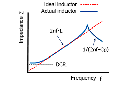
The graph shows a conceptual image of impedance characteristics of ideal and actual inductors with respect to frequency. The impedance of ideal inductors increases linearly with higher frequencies. However, in actual inductors, a self-resonance phenomenon occurs due to parasitic capacitance, and the impedance decreases at even higher frequencies, causing the inductors to lose their original function. Losses also occur due to resistance components and decreases in impedance.
Impedance (Z) of inductors is expressed by the following equation.
Z=R+1/(1/jωL+jωC)
The absolute value of impedance is calculated by the following equation
|Z|=√ R2+1/(1/ωL-ωC) 2
- Z
- : Impedance [Ω]
- R
- : DC resistance component
(DCR) [Ω] - C
- : Parasitic capacitance (Cp) [F]
- j
- : Imaginary number
- ω
- : 2πf
(π:Pi (3.14)、
f:Frequency [Hz]) - L
- : Inductance [H]
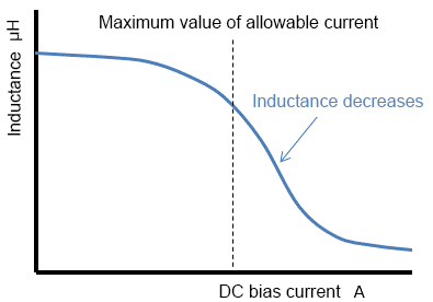
Magnetic saturation characteristics
Inductors become magnetically saturated when the flowing current exceeds the maximum value of the magnetic saturation allowable current (DC bias allowable current), resulting in a decrease in inductance. As shown by the impedance equation above, when inductors are saturated, impedance becomes small and the current flowing through them becomes abnormally large. As a result, for example, DC/DC converters may suffer lower efficiency and malfunction. Magnetic saturation allowable current is an important characteristic of inductors.
AC Resistance (ACR)(ACR)
Although only the DC resistance (DCR) was explained earlier in the impedance section, practical inductors also include resistance components that generate eddy current losses at the core and resistance components of conductive wires that increase due to skin and proximity effects. These components are referred to as AC resistances (ACR). AC resistances (ACR), whose value increases in proportion to frequencies, have a significant impact on power losses and increases in component temperature at high frequencies and therefore need to be taken into consideration in practical use. (Eddy current losses, skin effects, and proximity effects will be described later.)
Other Characteristics
Other characteristics of inductors and related terms are summarized below.
- Q factor (quality factor)
- : Q factor, which refers to the ratio of the inductive reactance to the resistance of an inductor at a specific frequency, is an index of inductor performance. The higher its Q factor, the closer an inductor is to an ideal inductor. The value obtained by dividing inductive reactance XL (= ωL = 2ΠfL) by ACR indicates the magnitude of a loss with respect to the frequency. The equation shows that Q is high when ACR is small.
- Copper losses
- : Losses due to resistance components when current flows through a conductive wire is referred to as a copper loss.
- Iron losses
- : Losses that occur in a core when a magnetic flux passes through it (hysteresis and eddy current losses) are referred to as iron losses.
- Skin effect
- : Increasing the frequency of current flowing through a conductor causes the current to flow only through the surface of the conductor, resulting in a higher current density at the surface section and thereby an increase in the resistance value. This is referred to as a skin effect.
- Proximity effect
- : When multiple conductive wires are in proximity to each other, the magnetic field formed by each wound wire induces an eddy current. At high frequencies, the current flow in each conductive wire concentrates in a narrow region that contacts an adjacent conductive wire, resulting in a higher current density at the proximity section and thereby an increase in the resistance value. This is referred to as a proximity effect.
- Eddy current losses
- : A magnetic field that changes due to electromagnetic induction generates an eddy current in the core of the conductor. The energy that generates this current is converted to heat as a loss due to the electric resistance of the core material. This is referred to as an eddy current loss.
- Hysteresis losses
- : Changing or reversing the magnetic field in a core will cause it to return to its original state with a hysteresis (hysteresis loop shown in BH diagrams of core materials). The energy consumed by this hysteresis action is lost as heat. This is referred to as a hysteresis loss, which is proportional to the area of the hysteresis loop.
Main Specifications of Inductors
The main specifications of inductors are shown below. Although various characteristics of inductors were explained in the previous section, not all the characteristics are designated as specifications. Here, typical characteristics specified in the datasheets of inductors are summarized. It should be noted that the availability of items and prescribed conditions differ by manufacturer and product, and it is therefore necessary to carefully check the notes, etc. of datasheets.
| Specification items | Meaning/condition, etc. |
|---|---|
| Inductance (L value) [μH] | Nominal inductance at a specific frequency |
| DC resistance (DCR) [Ω] | Resistance component of a conductor (copper wire) that constitutes an inductor |
| Rated current: temperature rise (ΔT) [A] | Rated current value at which the temperature rise when AC current is applied reaches 40 K |
| Rated current: DC bias (ΔL) [A] | Rated current at which the L value decreases from the initial value to the specified rate when DC current is applied (DC bias) |
"Inductance," which is obviously an essential item, indicates a value at a specified frequency and has a tolerance, e.g., ±30%.
"DC resistance," as explained earlier, consists mainly of the resistance of a wound wire and indicates a tolerance such as ±20%.
AC resistance (ACR), which was also explained as a resistance component, is often not indicated in specifications and must be checked with a manufacturer as necessary.
"Rated current" has two items. Although "temperature rise" often specifies the rated current at which the temperature rises by 40 K when DC current is applied, its condition may differ by manufacturer and product.
The other item "DC bias current" usually indicates the maximum current value at which the inductance becomes -30%, but the condition also differs by manufacturer and product.
Although the rated current is an important specification, not both items are always indicated. When only one of them is indicated, that rating is to be followed. However, it may be necessary to check with the manufacturer in some cases.
In addition to these items, the "self-resonant frequency" is sometimes specified. As described earlier, it indicates the limit frequency at which inductors are able to function properly as inductors.
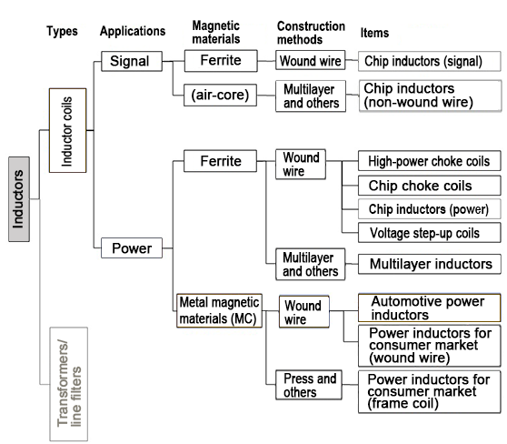
Types of Inductors
There are a variety of types of inductors, and their classification methods vary depending on perspectives. The diagram below divides applications into signal and power and classifies each category by magnetic (core) material and construction method.
Related product information
Tags related to this article

This document summarizes the Basic Knowledge of Inductors posted as technical information for the Optimal Solutions for Circuit Design.