Back Electromotive Voltage
Definition
Explanation
The magnitude of this voltage is expressed by the following equation:
V = −L × dI / dt
where L is the inductance and dI/dt is the rate of change of current (I is current and t is time). As indicated by the equation, the faster the current changes, the greater the back electromotive voltage that is generated.
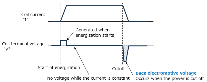
Back electromotive voltage becomes particularly problematic at the moment the current is interrupted. When a switching device cuts off the current, the rate of current change becomes extremely high, and the resulting back electromotive voltage can reach several times, or even up to ten times, the applied voltage. If this voltage is applied to a transistor or FET, it may exceed the device's withstand voltage and cause a breakdown. One well‑known example is a relay coil driven by a transistor, where the back electromotive voltage exceeds the rated collector‑emitter voltage and damages the transistor.
Back electromotive voltage is generated in a wide range of inductive loads that contain coils, including relays, solenoids, electromagnetic valves, DC motors, fan motors, transformers, and inductors. Therefore, circuits that drive coils or similar components must always be designed with countermeasures against back electromotive voltage as a basic requirement.
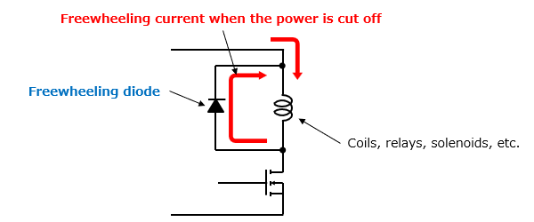
The most basic countermeasure is to connect a freewheeling diode (flywheel diode) in parallel with the coil. When the cathode is connected to the power‑supply side and the anode to the switching‑device side, the current that attempts to continue flowing through the coil at the moment of interruption circulates through the diode, dissipating the stored energy. As a result, the voltage across the switching device is limited to approximately the diode’s forward voltage, preventing excessive voltage from being applied.
In applications where response speed is a priority, relying solely on a freewheeling diode may result in slow current decay. In such cases, a Zener diode can be used to raise the voltage clamp level, or an RC snubber circuit consisting of a resistor and capacitor may be added. The appropriate method should be selected by balancing the required voltage suppression against the allowable turn‑off time.