Basic Knowledge of Inertial Sensors
- Gyro Sensors and Acceleration sensors -
2020-09-23
Today, cars have countless sensors to meet demands for self-driving, improved safety, and more comfortability.
Among these sensors, inertial sensors, such as gyro sensors and acceleration sensors, are attracting a great deal of attention.
This article will discuss the basics of gyro sensors and acceleration sensors.
Gyro sensor
What is a gyro sensor?
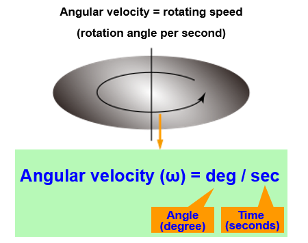
A gyro sensor, which is also referred to as an angular velocity sensor, detects the rotation or a directional change of an object as angular velocity, using a measurement of the Coriolis force, then outputs the detected angular velocity in the form of an electric signal.
In other words, an angular velocity is given by dividing an angle by time and is expressed in "dps" (degree per second).
For example, the angular velocity of an object that makes one rotation in 60 seconds is given as 360 deg. ÷ 60 sec. = 6 dps.
Coriolis force
To understand a gyro sensor, you need to know the Coriolis force first.
The Coriolis force is an apparent force acting on a moving object in a rotating system.
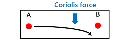
Here is an example that helps you understand what the Coriolis force is. See the diagrams on the right below showing a ball thrown from point A to point B. Analyzing the trajectory of this ball will give you an idea of the Coriolis force.
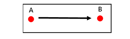
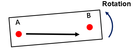
This apparent force skewing the ball is called Coriolis force.
The Coriolis force is given by the following equation.
F =2mvω
From this equation, the angular velocity is derived in the following manner.
ω =F/2mv
- F
- : Coriolis force (N)
- m
- : Mass of an object (kg)
- v
- : Traveling speed (m/s)
- ω
- : Angular velocity (dps)
As you see, measurement of the Coriolis force allows calculation of the angular velocity.
Mechanism of a vibration type gyro sensor
Now let's talk about the mechanism of a vibration type gyro sensor, a type of gyro sensor that is the most popular among gyro sensor varieties.
According to the vibration type gyro sensor, a vibrator in its vibrating state rotates to generate a Coriolis force, which is detected to determine an angular velocity.
The vibration type gyro sensor adopts different methods of detecting the Coriolis force, such as a piezoelectric detection method and a capacitance detection method.
- Piezoelectric detection method
The piezoelectric detection method works in the following manner.
First, a vibrator in a non-rotated state is caused to vibrate at a certain cycle in the X-axis direction, as shown in Fig. a). This could be interpreted as a state analogous to the state mentioned above where the ball is thrown from point A to point B. The vibrator is then put into rotation.
As shown in Fig. b), the rotation generates a Coriolis force in the Y-axis direction, which bends the vibrator in the Y-axis direction, creating a piezoelectric effect, which generates a voltage.
This voltage is measured to determine the Coriolis force and then determine the corresponding angular velocity.a) Vibrator in a non-rotated state 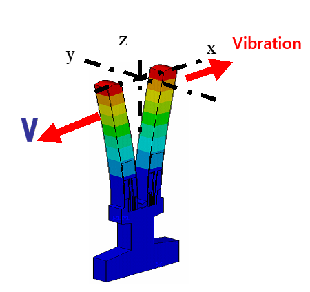
b) Vibrator in a rotated state 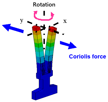
- Capacitance detection method
Now let's see how the capacitance detection method works.
First, a vibrator in a non-rotated state is caused to vibrate at a certain cycle in the X-axis direction by applying a square waveform voltage across drive electrodes, as shown in Fig. c).
At this time, capacitances C1 and C2 are formed respectively between detection electrodes and the vibrator that are kept equal.
The vibrator in this condition is then put into rotation. As shown in Fig. d), the rotation generates a Coriolis force in the Y-axis direction, which shifts the vibrator in the Y-axis direction.
This creates a difference between the capacitance C1 and the capacitance C2 (C1≠C2), which are formed respectively between the detection electrodes and the vibrator.
This capacitance difference is measured to determine the Coriolis force and then determine the corresponding angular velocity.c) Vibrator in a non-rotated state 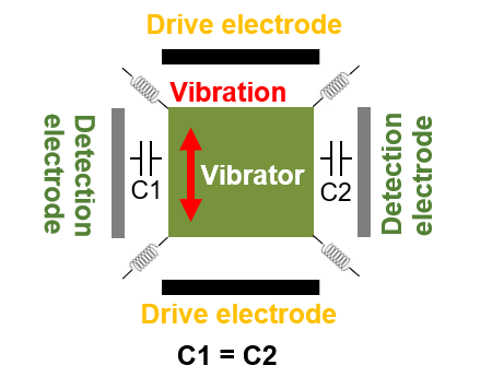
d) Vibrator in a rotated state 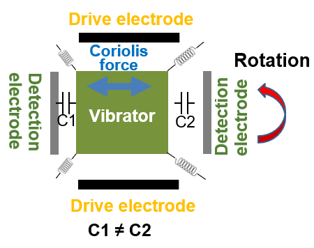
Gyro sensor usage
The gyro sensor detects a movement (rotation) of an object and displays the movement, corrects the movement, or causes the object to make another movement in response to the detected movement.
Use examples for each action are shown below.
- Display a movement: car navigation system, etc.
In a place where radio communication is lost, the gyro sensor detects and displays a direction in which the car has made a turn. - Correct a movement: stabilizing a camera image, etc.
Detecting a shake of the camera (a change in a lens angle) at the time of photographing, the gyro sensor corrects a lens angle to cancel out image disturbance. - Cause an object to make another movement in response to a detected movement: actuating a side airbag, preventing a sideslip (ESC), etc.
Detecting the car's turning over on its side, the gyro sensor actuates a side airbag. When detecting a sideslip of the car, the gyro sensor controls the movement of four wheels to maintain the stable position of the car.
Acceleration sensor
What is an acceleration sensor?
An acceleration sensor detects the inertial force generated when the traveling speed of an object changes, and outputs acceleration corresponding to the detected inertial force in the form of an electric signal.
Acceleration is a rate of change of speed per unit time.
The following is the simplest formula for acceleration.
a=(v2-v1)/t
- a
- : Acceleration (m/s2)
- v1
- : The speed at point 1 (m/s)
- v2
- : The speed at point 2 (m/s)
- t
- : Time required for travel from point 1 to point 2 (s)
This formula states that when an object travels from point 1, at which the speed of the object is v1, to point 2, at which the speed of the object has changed to v2, in a time t, the object has an acceleration defined to be (v2-v1)/t.
This holds true provided that the acceleration remains constant in the section between point 1 and point 2.
The acceleration correlates with an inertial force.
Let's say, for example, that you are in a car.
When the car starts (accelerates), you would feel being pushed backward. When the car comes into a stop (decelerates), in contrast, you would feel being pushed forward.
This happens because an inertial force comes to work every time the speed of an object changes, that is, the object accelerates or decelerates.
The relationship between the inertial force and the acceleration is defined by the following equation.
F=m×a
'This equation can be modified into the following.
a=F/m
- F
- : Inertial force (N)
- m
- : Mass of an object (kg)
- a
- : Acceleration (m/s2)
As you can see, measuring the inertial force F allows you to determine the acceleration.
Note, however, that actual acceleration values are expressed in terms of gravitational acceleration (G) in many cases.
1.0G = 9.8m/s2
With proper signal processing, the acceleration sensor also provides information on gravity, vibrations, impact, etc., in addition to information on acceleration (movement).
Mechanism of the acceleration sensor
The acceleration sensor is similar in basic structure to the gyro sensor described in the previous section, and detects acceleration by a piezoelectric detection method, capacitance detection method, etc., in the same manner as the gyro sensor detects the angular velocity.
Here, we will examine how the acceleration sensor detects acceleration using the capacitance detection method.
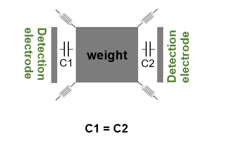
When the acceleration sensor is subjected to no acceleration, a weight lies at the midpoint between detection electrodes on both sides, as shown in Fig. a), in which case the capacitance at C1 and capacitance at C2, formed respectively between the weight and the detection electrodes, are equal to each other.
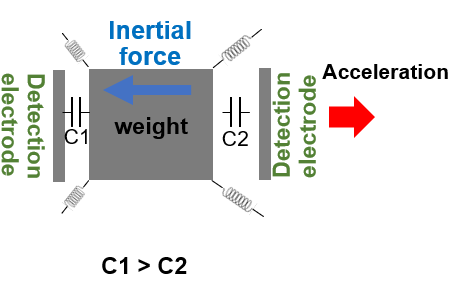
When acceleration is applied to the acceleration sensor in a direction shown in Fig. b), however, an inertial force is generated in the direction opposite to the direction of the acceleration, which causes the weight to shift in the Y-axis direction.
This creates a difference between the capacitance at C1 and the capacitance at C2, formed respectively between the weight and the detection electrodes, the capacitance at C1 becomes larger than the capacitance at C2.
This capacitance difference is measured to determine the inertial force and then determine the acceleration.
Acceleration sensor usage
The acceleration sensor can detect movement, gravity, vibration, and impact and is therefore used for various applications requiring information on movement, gravity, vibration, and impact.
- Detect a movement: car navigation system, etc.
In a place where radio communication is lost, the acceleration sensor determines the traveling distance of a car from the change in the acceleration of the car and displays the traveling distance. - Detect the gravity: changing the position of the smartphone monitor, etc.
Detecting a change in the gravitational acceleration to recognize a smartphone's tilt, the acceleration sensor causes the smartphone monitor to switch to landscape mode or portrait mode. - Detect vibration: seismometer, etc.
Detecting a change in acceleration in the direction of vibration, the acceleration sensor determines the magnitude and intensity of an earthquake and displays/records the magnitude and intensity. - Detect impact: airbag, etc.
The acceleration sensor determines the magnitude of impact from a change in acceleration and actuates a car's airbag.
Gyro sensor plus acceleration sensor
So far, we have discussed the gyro sensor and acceleration sensor separately. The gyro sensor or acceleration sensor alone, however, cannot detect complicated motions of an object.
For example, a car navigation system includes a gyro sensor that detects a traveling direction and an acceleration sensor that detects a traveling distance, thus correctly displaying the current position of the car in a place where radio communication is lost.
The number of such devices equipped with both gyro sensor and acceleration sensor has been increasing lately.
Directions of detection have also been increasing. Now sensors are set not along a single axis but two axes (x and y directions) or three axes (x, y, and z directions). This allows the sensors to gather more information and detect the movement of an object more precisely.
However, setting pairs of gyro sensors and acceleration sensors along three axes brings the total number of sensors to six.
Such a configuration is difficult to adopt from space or cost point of view. There is another concern that a variation in individual sensors' setting locations may lead to lower precision in data acquisition.
In recent years, to deal with such problems, a multi-axis gyro sensor or acceleration sensor with an integrated structure and a multi-axis inertial sensor constructed by combing a gyro sensor and an acceleration sensor together have been put on the market.
Panasonic too has released an automotive six-axis inertial sensor (6-in-1 sensor), in which gyro sensors along three axes and acceleration sensors along three axes are packaged in a single chip. This product will meet the market demand for a small-sized, high-precision sensor.
Related product information
Tags related to this article
This document summarizes the Basic knowledge of Inertial Sensors posted as technical information for the Optimal Solutions for Circuit Design.
