Chip resistor’s failure phenomenon/mechanism
and solutions (1)
2021-09-27
Chip resistors are rarely break down compared to other electronic components, but they still generate failures caused by excessive load or under severe operating environments.
This article discusses failure phenomenon and mechanism of chip resistors along with their solutions.
Outline of failure phenomena
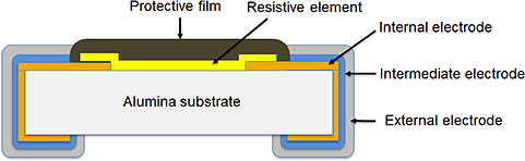
Chip resistor failure phenomena can be briefly divided into seven groups as shown in the table below, and their failure modes are resistance value increase/open circuit (wire breakage) and resistance value decrease/short circuit.
| No. | Failure phenomenon | Usage Environment | Failure position | Applicable chip Resistor type |
Failure mode |
|---|---|---|---|---|---|
| 1 | Migration | Halogen composition attachment | Internal electrode | All | Resistance value reduction, shorted circuit |
| 2 | Electrolytic Corrosion | Resistive element | Thin film type | Resistance value increase, / open circuit (wire breakage) |
|
| Environment containing sulfur | Resistive element | Thin film type | |||
| 3 | Sulfurization | Internal electrode | All | ||
| 4 | Electrode separation | Excessive mechanical stress | Intermediate electrode | All | |
| 5 | Solder Crack | The solder used for circuit mounting | All | ||
| 6 | Resistive element burnout | Electrical overload | Resistive element | All | |
| 7 | Resistive Element Deterioration | Resistive element | Thick film type | Resistance value reduction |
Actual failures are primarily resistance value increase/open circuit (wire breakage).
Next section describes failure phenomena with their mechanism and solutions in detail.
Migration
Migration mechanism
Migration is generally a phenomenon occurring with a pair of electrodes placed in a high humidity environment. When voltage is applied between these electrodes, the anode metal is ionized and moves to the facing cathode and regenerates as metal again.
The metal generated on the cathode grows into a tree-like shape and reduces insulation between poles, eventually causing a short-circuit.
Migration generally occurs when the three factors of electricity, water and halogen substance co-exist, by generating “Sn migration” on the exterior (solder) of the electronic component and “Ag migration” generated within the component.
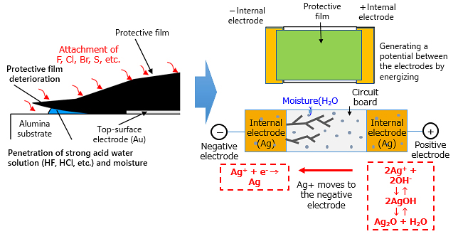
As the Ag electrode is fully covered with a protective membrane or plating, Ag migration isn’t generated in a normal operating environment. But when halogen substances (F, Cl, Br) contained in flux etc. attaches with an active force, it causes deterioration of the protective membrane, and when moisture and an electric potential exists, migration may be happen.
Method of solving migration
The following two methods can be applied for preventing migration.
- (1) Remove halogen substance residue with a non-halogen cleaning agent.
- (2) When using flux or adhesive, use the appropriate heat treatment* to make halogen substances inactive.
* For detailed heat treatment conditions, consult with each flux or adhesive manufacturer.
electrolytic corrosion
Electrolytic corrosion may be caused by halogen component or sulfur component.
Mechanism of electrolytic corrosion
As described in migration, when a halogen substance (F, Cl, Br) residue, contained in flux, adhesive, or cleaning agent, attaches to the surface of a chip resistor, and is exposed to a sulfur-containing atmosphere, the chip resistor surface protection membrane deteriorates, and moisture in the atmosphere containing halogen and sulfur tend to penetrate in the resistive element.
As thin-film chip resistors use a nickel-chrome alloy (Ni-Cr), the resistor element can be corroded by the penetrating moisture containing halogen and sulfur, leading to a resistance value increase and open circuit (wire breakage).
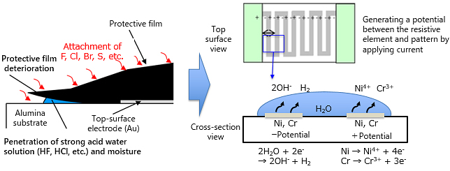
Thick film chip resistors consist of a resistive element made from a sintered mixture of ruthenium oxide and glass, and therefore free from electrolytic corrosion.
Method of solving electrolytic corrosion
The following three methods are applicable in avoiding electrolytic corrosion.
- (1) Remove halogen substance residue with a non-halogen cleaning agent.
- (2) When using flux or adhesive, employ the appropriate heat treatment* to make halogen substances inactivate.
*For detailed heat treatment conditions, consult with each flux or adhesive manufacturer.
- (3) Remove or isolate from a sulfur-containing atmosphere.
Sulfurization
When a chip resistor is exposed to a sulfur-containing atmosphere, its internal electrodes deteriorate. This is called sulfurization. Sulfurization occurs with products using silver-based metal for internal electrodes, and failures by sulfurization occur in both the thick-film type and thin-film type.
Sulfurization mechanism
When a chip resistor is exposed to a sulfur-containing atmosphere, sulfur content penetrates through the gap between the protective film and plating. When the sulfur content reaches the internal electrodes (silver), silver (Ag) and sulfur (S) cause a chemical reaction and form an insulating substance (Ag2S), thereby corroding internal electrodes and increasing the resistance value, eventually causing an open circuit (wire breakage).
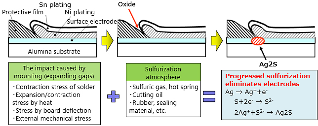
Locations that have a sulfur-rich atmosphere include areas near a volcano or hot spring, automobile exhaust gas, and environments using cutting oil or rubber products. Even in a general environment, some materials sometime contain sulfur content. For example, cooling fan filters, rubber products and sponges used for packing and vibration prevention, even silicon-based coating agent may promote sulfurization.
Sulfurization solution method
The following three methods are thought effective for preventing sulfurization.
- (1) Remove or isolate from sulfur-containing atmosphere.
- (2) Do not use sulfur-containing materials.
- (3) Select components that are strong against sulfur contents.
The most effective method for preventing sulfurization is (3) selecting components highly resistant to sulfur content.
Our company offers a product lineup of “Anti-sulfurization chip resistors” using high palladium-silver electrodes and gold electrodes that are highly resistant to sulfurization.
This article described “Outline of failure phenomena” along with “Migration”, “Electrolytic corrosion” and “Sulfurization”.
The next issue provides explanation of the four items from “Electrode peel-off” to “Resistive element deterioration”.
Related information
Related product information
Tags related to this article
This document summarizes the Chip resistor’s failure phenomenon/mechanism and solutions posted as technical information for the Optimal Solutions for Circuit Design.
