Using chip resistors in an environment exceeding their product specifications may cause failures such as an increase in resistance value or an open circuit (wire breakage), or a reduction in resistance value or a short circuit. Use caution and refer to the table shown below. Before using the products, also check Caution Items for Safety. Caution Items for Safety .
* Click each failure phenomenon to move to the explanation.
| Usage Environment | Failure phenomenon | Failure Mode | ||||||||||||||||
| Chemical Cause |
Electrical Cause |
Physical Cause |
||||||||||||||||
| Attachment of halogen components |
Resistance value reduction, short circuit |
|||||||||||||||||
| *Case: Flux Post-flux Adhesive, etc. |
||||||||||||||||||
| Resistance value increase, open circuit (wire breakage) |
||||||||||||||||||
| Environment containing sulfur |
||||||||||||||||||
| *Cases: Volcano, hot-spring area Exhaust gas, Oil vulcanized rubber, etc. |
||||||||||||||||||
| Excessive mechanical stress |
||||||||||||||||||
| *Cases: Excessive solder quantity Excessive reflow profile Molded resin, etc. |
||||||||||||||||||
| Electrical overload | ||||||||||||||||||
| *Cases: Voltage/current Static electricity Pulse, etc. |
||||||||||||||||||
| Resistance value reduction | ||||||||||||||||||

Migration
Migration is a phenomenon of ionized metal in the positive electrode moving to the negative electrode and regenerating tree-shaped metal material.
Migration is a possible failure phenomenon generated when the following three conditions occur at the same time: inclusion of halogen ingredients in the flux or adhesive used in the circuit mounting process at the customer's side, inclusion of moisture in the market environment, and an electric current applied to a resistor.
| Applicable products | Resistors in general (electronic components in general) |
|---|---|
| Failure mode | Resistance value reduction, shorted circuit |
| Failure phenomenon | Migration (Metals grow in a tree shape from the negative electrode toward the positive electrode) |
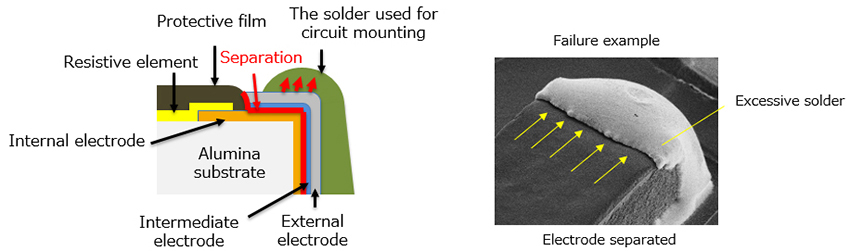
| Failure mechanism | When halogen components (F, Cl, Br, etc.) attach to a resistor and remain in an active condition, it causes deterioration (separation) of the protective film. The moisture that penetrates from the deteriorated part and electrical potential generate migration of the internal electrodes. *Migration also occurs outside of a resistor (Sn in solder). |
 |
|
| Solution | ・Remove halogen components by using a non-halogen cleaning agent. ・When using flux or adhesive, apply heat treatment to deactivate halogen substances. *Be sure to apply one of the two items shown above. |
Electrolytic Corrosion
Electrolytic corrosion is a possible failure phenomenon that can occur when three factors are compounded: inclusion of halogen components contained in the flux or adhesive used in the circuit mounting process at the customer's side, inclusion of moisture in the market environment, and electric current in the resistor.
| Applicable products | Thin-film resistors in general having extremely thin nickel-chrome alloy resistance |
|---|---|
| Failure mode | Resistance value increase, open circuit (wire breakage) |
| Failure phenomenon | Electrolytic corrosion |
| Failure mechanism | When halogen components (F, Cl, Br, etc.) or sulphidizing (S) gas is attached to a resistor in an active condition, deterioration (peel-off) of the protective film leads to moisture penetration at the deteriorated part and the electrical potential, which generate electrolytic corrosion of the resistive element (NiCr substance). |
 |
|
| Solution | ・Remove halogen components by using a non-halogen cleaning agent. ・When using flux or adhesive, apply an appropriate heat treatment for deactivating halogen substances. *Be sure to apply one of the two above. ・Eliminate or isolate sulfur-containing atmosphere. *Be sure to execute the procedures above. |
| Failure example | As an actual example, a failure shown below is occurring. When using the product, check if this type of risk is remaining. |
Case 1: Incorrect heat treatment for applied post-flux during flow-soldering causes halogen activity to remain and generate electrolytic corrosion.

[1] Remove flux by cleaning
[2] Complete curing of flux at 230℃ or higher (for eliminating halogen activity)
Applying insufficient temperature (100 to 150℃) may increase halogen activity – Use caution.
[3] Prevent splashing of flux on nearby components during application
Case 2: Generation of electrolytic corrosion caused by materials containing halogen

[1] Analyze materials in advance and confirm that they do not contain halogens
[2] Apply complete curing of the adhesive at 230℃C or higher (for eliminating active power of halogen)
Sulfurization
Sulfurization is a phenomenon causing electrolytic corrosion of internal electrodes by sulfuric components.
Sulfurization is a failure phenomenon generated when the top surface of an electrode is exposed by stress during the mounting process, and then to a sulfuric atmosphere.
| Applicable products | Chip resistors in general containing silver in the internal electrodes |
|---|---|
| Failure mode | Resistance value increase, open circuit (wire breakage) |
| Failure phenomenon | Electrolytic corrosion |
| Failure mechanism | Sulfuric components (S) penetrate a gap between the protective membrane and plating, and activate with internal electrodes (silver: Ag) to generate silver sulfide (Ag2S) by turning to insulation material. |
  |
|
| Solution | Remove sulfur-contained atmosphere, or isolate from it Do not use sulfur-contained materials. |
Electrode Separation
Electrode separation is a failure phenomenon generated by mechanical stress such as excessive solder quantity, thermal impact exceeding the recommended reflow profile, molded resin curing compression, etc.
| Applicable products | Chip resistors in general |
|---|---|
| Failure mode | Resistance value increase, open circuit (wire breakage) |
| Failure phenomenon | Electrode separation by soldering stress |
| Failure mechanism | Intermediate electrode separates by excessive solder shrinkage, printed board warping, or molded resin curing and shrinkage, during reflow soldering. |
 |
|
| Solution | ・Select appropriate soldering condition (Refer to individual product specification) ・Apply appropriate solder quantity during the mounting (Refer to the following) |
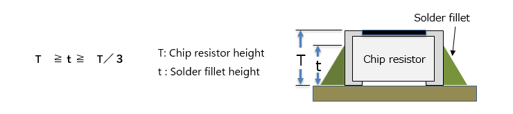 |
|
Solder Crack
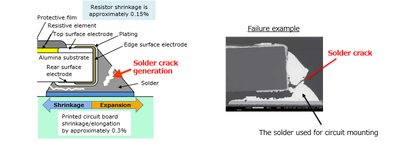
Solder crack is a failure phenomenon caused primarily by thermal impact stress in the user’s operating condition.
| Applicable products | Chip resistors in general |
|---|---|
| Failure mode | Resistance value increase, open circuit (wire breakage) |
| Failure phenomenon | Solder cracking caused by the difference in thermal expansion coefficient (solder fatigue) |
| Failure mechanism | When thermal impact stress is further applied, solder cracking is generated by the difference in thermal expansion coefficient between a printed circuit board (PCB) and a resistor. |
 |
|
| Solution | ・After identifying possible thermal impact to be applied, select the appropriate materials (PCB, solder) to be used. *As a solder cracking prevention measure, measures such as increasing solder quantity or solder hardness may increase stress in electronic components and could generate failures such as electrode peel-off so that they are not appropriate actions. (Because all of the stress received by solder joints are applied to all electronic components) |
Damage to Resistive Element
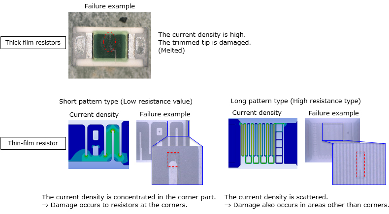
Damage to resistive elements is a failure phenomenon generated from overload, excessive ESD, excessive surge pulse, etc.
| Applicable products | Chip resistors in general |
|---|---|
| Failure mode | Resistance value increase, open circuit (wire breakage) |
| Failure phenomenon | Resistive element damage caused by electrical overload |
| Failure mechanism | Overload, excessive ESD, or excessive surge pulse causes a large instantaneous current to cause heat generation or damage of resistive element, leading to increase of resistance value, and wire breakage (open circuit). |
 |
|
| Solution | ・ESD control by using a resistor ・Circuit design without exceeding the limit load of a resistor * Please contact us for details |
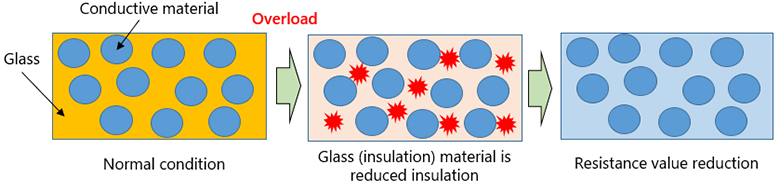
Resistive Element Deterioration
Resistive element deterioration is a failure phenomenon caused by overload in an extremely short time, excessive ESD, excessive surge pulse, etc.
| Applicable products | Chip resistor using glass-contained resistance film (thick film resistor) |
|---|---|
| Failure mode | Resistance value reduction |
| Failure phenomenon | Resistive element deterioration caused by electrical overload |
| Failure mechanism | Overload in an extremely short time, excessive ESD, or excessive surge pulse destroys the insulation component (glass) of the resistance film and reduces the resistance value. |
 |
|
| Solution | ・ESD control by using a resistor ・Circuit design without exceeding the limit load of a resistor *Please contact us for details |