⑧ How to select a common mode filter 1
This section describes how to select a common mode filter.
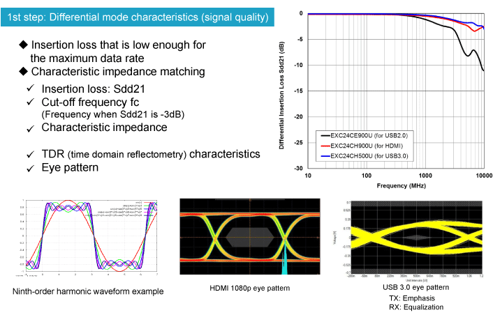
Basically, there are two steps for the selection: checking the performance to prevent the attenuation of digital signals; and checking the performance to attenuate noise.
Firstly, select a filter with a low differential mode insertion loss in order to pass digital signals without loss. As shown in the figure below, at least a third-order to fifth-order harmonic component is required to shape a digital signal waveform. Therefore, when the fundamental frequency of a digital signal is f0, a filter having a cut-off frequency of 3xf0 or 5xf0 or higher is normally selected.
For today's high-speed transmission, however, many interfaces are designed to execute emphasis processing at the output end and equalization at the receiving end in order to compensate for the harmonic component loss. In such cases, a filter having a cut-off frequency of less than 3xf0 may be adopted if it passes specified compliance tests and doesn’t show any problems during actual use.
Matching of differential mode characteristic impedance
Another key parameter of differential mode transmission is differential mode characteristic impedance (hereafter, characteristic impedance).
Generally, transmission lines are designed according to the characteristic impedance specified by the applicable interface standards. In the case of USB, for example, the specified characteristic impedance is 90 Ω. For HDMI, it is 100 Ω.
If the characteristic impedance of a common mode noise filter deviates significantly from the specified value in a transmission frequency band, then this will result in reflections and losses of the differential signals, thereby degrading the signals.
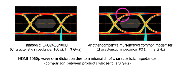
The figures below show the results of HDMI 1080p eye mask tests of two common mode filters having the same cut-off frequency (3 GHz) and different characteristic impedance.
Another company's filter whose characteristic impedance is 80 Ω, which is lower than that of our product (100 Ω), shows signal degradation.
This indicates that matching of the differential mode characteristic impedance should also be taken into account.
The characteristic impedance matching can be evaluated by TDR, which is a time-based measurement, or by S-parameters, which are based on frequencies
You can obtain frequency-based characteristic impedance information of common mode filters by using the calculations of S-parameters we provide.
TDR is a method of measuring differential mode characteristic impedance by inputting a step pulse from the connector side and observing the response. When a line under test has a part whose characteristic impedance is different from that of the inputted step pulse, i.e., the specified characteristic impedance, the part causes reflections and losses. The results are converted into characteristic impedance values and provided as information about the line. One of the advantages of TDR is that the characteristic impedance can be observed together with the location information using a finished product, allowing for the identification of any mismatched part on the circuit board.
Evaluation of the matching of differential mode characteristic impedance by TDR
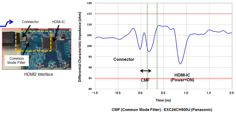
As an example of TDR, the graph below shows the TDR characteristics of our common mode filter in an HDMI interface. The graph indicates that you can obtain the characteristic impedance values of respective parts, i.e., the connector, common mode filter, and HDMI-IC.
The characteristic impedance of our common mode filter is well within the specification for HDMI transmission lines (100 Ω +/- 15 Ω), indicating excellent impedance matching for differential transmission.
⑨ How to select a common mode filter 2
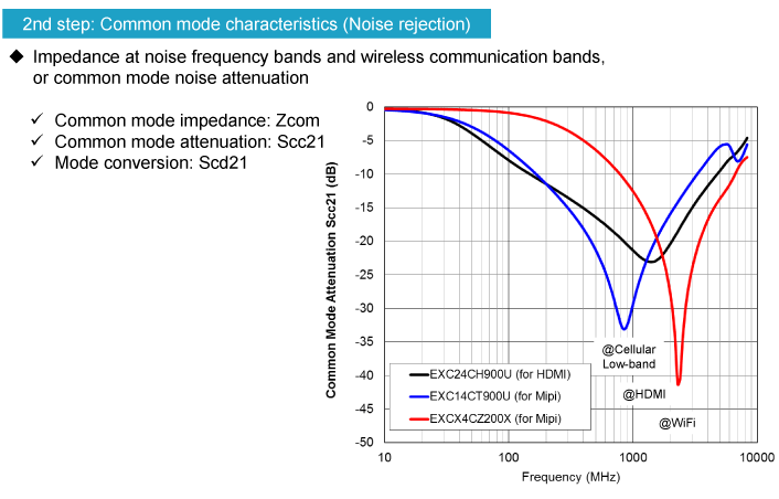
Secondly, select a filter with the frequency characteristics of common mode noise attenuation that allow the effective rejection of common mode noise at the target frequency band.
We offer a wide selection of filters from which you can find the best one for your purpose of use. For example, we have filters capable of significantly attenuating noise at wireless communication frequency bands as shown in the graph below, which are ideal for smartphones. We also have filters suitable for HDMI and other applications that require noise attenuation across a wide bandwidth.
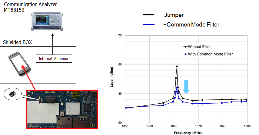
⑩ Example of improving the receiving sensitivity of smartphones
The following shows an example of measuring the cellular receiving sensitivity of a smartphone with our common mode filter.
In this example, our common mode filter located at the MIPI interface of the LCD suppresses the noise emitted from the flexible cable, thereby improving the receiving sensitivity.