Chip resistors that are smaller but which provide more advanced functions are now an important component in solving problems.
2017-10-13
What is a resistor?
A resistor, like a capacitor or inductor, is a fundamental element in many electrical circuits. Many resistors are incorporated in all sorts of electric/electronic devices.
This knowledge is so common to electric engineers/technicians, etc., that they may often take resistors completely for granted in their daily work. Nevertheless, no electric circuit will works without them. They are absolutely crucial.
Roles of a resistor
A resistor plays four major roles: current control, voltage dividing, current detection, and biasing.
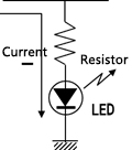
Current control
A resistor controls the current flowing through an electronic circuit, keeping it equal to or smaller than the rated current. In an LED circuit, for example, a resistor is connected in series to an LED to keep the circuit current equal to or smaller than the rated current, thereby preventing burnout of the LED.
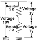
Voltage dividing
Two or more resistors connected in series divides an applied voltage into voltages that are proportional to the resistance values of the resistors. Two or more resistors connected in parallel, on the other hand, divides the current.
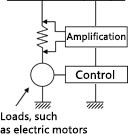
Current detection
:When a current flows through a resistor, a voltage that forces the current to flow through is applied across both ends of the resistor. Measuring this voltage tells you how much current is flowing through the circuit.
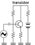
Biasing
Applying a voltage that causes a semiconductor, such as transistor, to operate is referred to as "biasing." Biasing is carried out such that different voltages are applied to different terminals (the emitter, collector, and base) of a transistor, respectively.
In addition to resistors exerting the above functions, there also are damping resistance, terminal resistance, and pull-up/pull-down resistors.
The resistor operates according to Ohm's law: Voltage (V) = Current (I) × Resistance (R)" In current detection by a resistor, a current is given by substituting a known resistance value and a voltage value across both ends of the resistor in the equation: “Current (I) = Voltage (V)/Resistance (R).”
Principle of the resistor
A resistor's value is determined by the natural resistance, sectional area, and length of the resistance material.
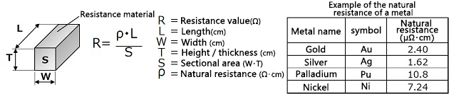
As indicated by the equation, the resistance value is given by dividing the product of the natural resistance ρ (Ω·cm) and the length L by the sectional area S. The following is an example of the natural resistance of a metal.
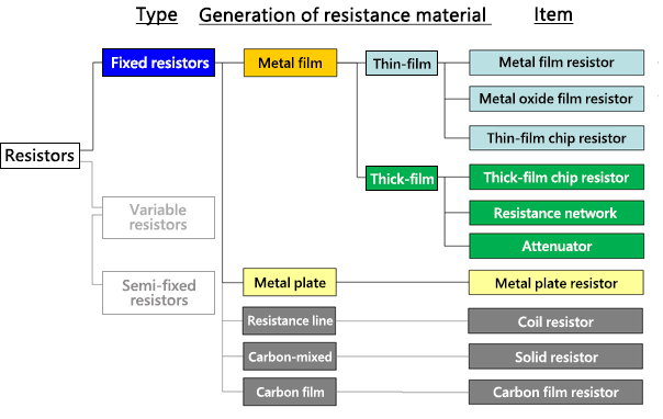
Types of resistors
Resistors are roughly classified into fixed resistors, variable resistors, and semi-fixed resistors. Looking at these resistors from a materials perspective, we have carbon-based resistors and metallic resistors. Resistance materials are formed as films, linear patterns, or tabular shapes, among which metal films include thin films and thick films. The following chart shows resistance categories.
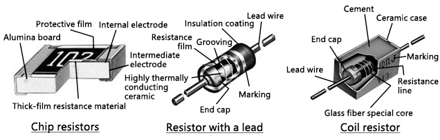
Structure of the resistor
The following diagram depicts the basic structure of a typical resistor. Various types of resistors are used for different purposes, but chip resistors are increasingly favored for use in small devices.
Panasonic's history of resistor manufacturing
Panasonic has an 85-year history of resistor manufacturing.
Following Konosuke Matsushita's motto, "Good parts create good products," in 1933, Panasonic started manufacturing a carbon film resistor for use in radio receivers. Resistor production grew in subsequent years, reaching 2 trillion units in total in 2013.
If the total number of ordinary 1608-size resistors manufactured by Panasonic were stacked up, they would reach to the moon and back, approximately 393 thousand kilometers.
Most of them would, however, be quite new. Production of chip resistors, which are a core product, increased explosively in the 1990s. This demonstrates the fact that the chip resistor is a component for which demand expanded sharply in response to the rapid development and popularity of digital household appliances.
Trends of chip resistors
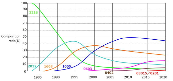
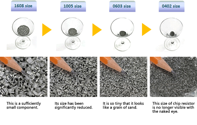
Size trends of chip resistors
In response to the rising demand for miniaturization of electronic devices, Panasonic has been making efforts to reduce the sizes of chip resistors. In the 25 years since the 3216 size was developed, the company has reduced the chip area to 1/64 (0402 size) and is further pushing ahead with miniaturization. The following graph depicts the progress of miniaturization of chip resistors and yearly changes in composition ratio of their size. Currently, 1005 size chip resistors account for nearly half of all chip resistors. However, production of the 1005 size is already showing a downturn as the demand for even smaller types grows.
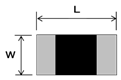
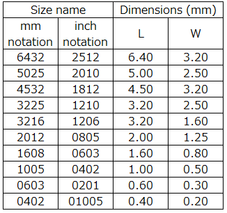
(Size name and dimensions)
A chip resistor's outer dimensions are usually expressed with four digits that represent "length (L) × width (W).
Example: 1.00 mm × 0.50 mm→1005
Chip resistors with improved features
There is a growing demand for chip resistors with improved features, with products using chip resistors showing ever-improving performance and with changes in the service environment.
To meet this market demand, Panasonic has developed a range of products with improved features.
(1) Anti-Sulfurated Chip Resistors
An ordinary chip resistor has an internal electrode made of silver. In a sulfur-containing atmosphere, the silver making up the internal electrode reacts with sulfur and produces silver sulfide, which is an insulating material. This may result in wire breakage.
For this reason, a chip resistor used in a sulfur-containing atmosphere or kept near materials containing sulfur must be provided with a means of ensuring resistance to sulfidation.

(2) Anti-Surge, Anti-pulse Chip Resistors
A chip resistor incorporated in a switching circuit or circuit exposed to the influence of static electricity, in which surge or pulse currents are applied frequently to the resistor, must be able to withstand them.

(3) High Precision Chip Resistors
A chip resistor incorporated in precision equipment, such as measuring devices and controllers, must be a high-precision type that shows little variation in resistance value (resistance allowance) or minimal temperature-dependent changes in resistance value (resistance temperature coefficient).

(4) Current Sensing Chip Resistors
A chip resistor for current detection is used to detect overcurrent or remaining battery capacity.
In recent years, electronic devices with higher functions have led to an increase in current flows in circuits. This has created a demand for a chip resistor capable of handling higher power levels.
Lower resistance for less power consumption in circuits is also required. High-precision resistors that retain a superior resistance temperature coefficient in harsh temperature environments are in high demand.

Supplementary information
Technical terms for resistors
A resistor has parameters representing its specifications and ratings. Here is a list of technical terms for such parameters. The four parameters in bold font are basic parameters for resistors.
| Power Rating (W) | Maximum power that can be applied continuously to the resistor at the highest category temperature |
| Resistance value (Ω) | Resistance value standardized in conformance with public standards |
| Resistance tolerance (%) | Resistance tolerance value indicates the precision of the resistor |
| Temperature coefficient of resistance (×10-6/K) |
Change in resistance value that results in response to a change in ambient temperature |
| Maximum working voltage (V) | Maximum voltage that can be applied continuously to the resistor at the highest category temperature |
| Operating temperature range (˚C) | Ambient temperature range under which the resistor is operable |
| DC resistance value (Ω) | Resistance value that is measured when a DC voltage is applied to the resistor. This value represents the basic resistance of the resistor. |
| Withstand voltage (V) | Dielectric strength of a product protected with an insulating outer sheath |
| Insulation resistance (Ω) | Insulation property of a product protected with an insulating outer sheath |
| Solder heat resistance | Electrical/mechanical stability if immersed in solder |
| Moisture resistance | Time-dependent stability against moisture |
| Temperature cycling | Electrical/mechanical stability with temperature changes |
| Endurance (load) | Electrical/mechanical stability in the case of consecutive application of the rated voltage at the highest service temperature |
| Terminal strength | Mechanical strength achieved by mechanically reinforcing the terminal of a component with a lead |
| Vibration resistance | Electrical/mechanical stability against vibration |
| Fire resistance | Self-fire-extinguishing and non-ignition properties if overloaded |
Standards on expression of resistance values and resistance allowances
As mentioned in the above list of technical terms for resistance values, resistance values and allowances are expressed in conformity with the following standards.
IEC 60062:Marking codes for resistors and capacitors.
IEC 60063:Preferred number series for resistors and capacitors
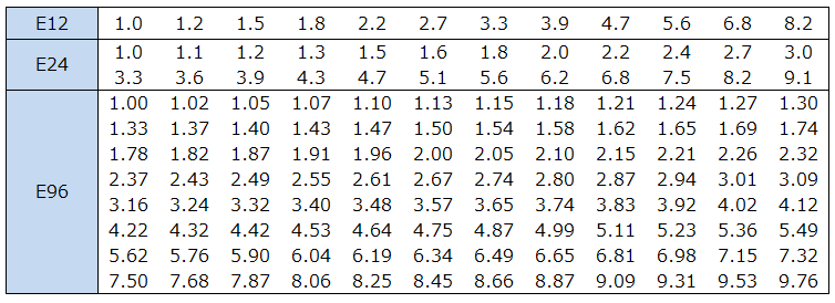
Resistance values are expressed as standardized numerical sequences according to the above standards. They are expressed not as integers such as 1 Ω, 2 Ω, and 3 Ω but as numbers with fractions, such as 2.2 Ω or 4.7 Ω. This is because resistance values are labeled according to the Electronic Industries Association (EIA)'s "Preferred Value" system (E system). "E" in this notation system stands for exponent, and the number following "E", e.g., 24, is the number of logarithmic steps per decade. E24 thus represents the value given by dividing 1 into 10 by a geometric series (root of 10 to the 24th). Resistors' resistance values are often applied in terms of ratios or percentages in actual cases. Resistance values in the form of numerical sequences are often more convenient than integers. The following is a list of resistance values expressed according to the notation system.
| series | Standardized resistance tolerance |
Common ratio |
|---|---|---|
| E12 | ±10% | 12 10 ≈ 1.21 |
| E24 | ±5% | 24 10 ≈ 1.10 |
| E96 | ±1% | 96 10 ≈ 1.02 |
Tags related to this article
This document summarizes the Chip resistors related articles posted as technical information for the Optimal Solutions for Circuit Design.
