Case Examples of Replacing Switching Power Supply Input/Output Capacitors from MLCCs to Hybrid Capacitors
2018-12-10
Introduction
In recent years, multi-layer ceramic capacitors (MLCCs) have often been used as the input and output capacitors of switching power supply circuits. Although MLCCs, which feature excellent ESR and ELS characteristics, are useful for switching power supplies, they are not without their issues such as large capacity, quantity, and costs. This article introduces case examples of replacing these MLCCs with conductive polymer hybrid aluminum electrolytic capacitors ("hybrid capacitors").
Replacing MLCCs Used as Input Capacitors of Switching Power Supply Circuits
The input of switching power supply circuits requires input capacitors usually referred to as CINs. The role of input capacitors is to allow ripple currents from discharges due to the switching of power transistors and charges from input power supplies, ripple currents due to fluctuations in input voltage, etc., to stabilize the input voltage, and reducing noise caused by these currents. Therefore, input capacitors require a ripple current rating compatible with the switching current, temperature rating including heat generation, low ESR (equivalent series resistance), etc. In general, MLCCs, aluminum electrolytic capacitors, etc., are used as input capacitors. In particular, small MLCCs, which possess excellent ESR and ESL (equivalent series inductance) characteristics, are often used as input capacitors. However, these MLCCs can be replaced with hybrid capacitors depending on the frequency characteristics of power supply circuits.
Hybrid capacitors, which are capacitors whose electrolyte is fused with conductive polymer and electrolyte liquid, possess excellent characteristics demonstrating the advantages of both conductive polymer and electrolyte liquid, as well as featuring a large capacity, low ESR, low leakage current, and high reliability.
・Case Example of Replacing MLCCs: Step-down DC/DC Converter in an Automotive ECU (Body Control Unit)
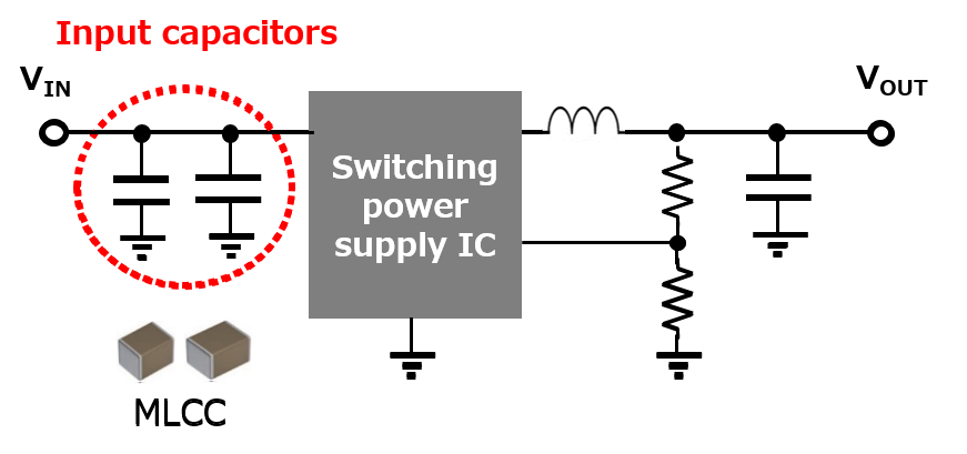
Here is a case example in which the input capacitor MLCCs of a switching power supply circuit were replaced with a hybrid capacitor. The switching frequency of this step-down DC/DC converter was 100 kHz - 300 kHz, and two 50-V, 10-µF (3225 mm) MLCCs, which have relatively large capacitance, were used as input capacitors. These MLCCs could be replaced with one 50-V, 22-µF (Φ6.3 x 5.8 mm) hybrid capacitor.
50V 10uF x 2pcs
(3.2x2.5mm)
50V 22uF x 1pc
(ø6.3x5.8mm)
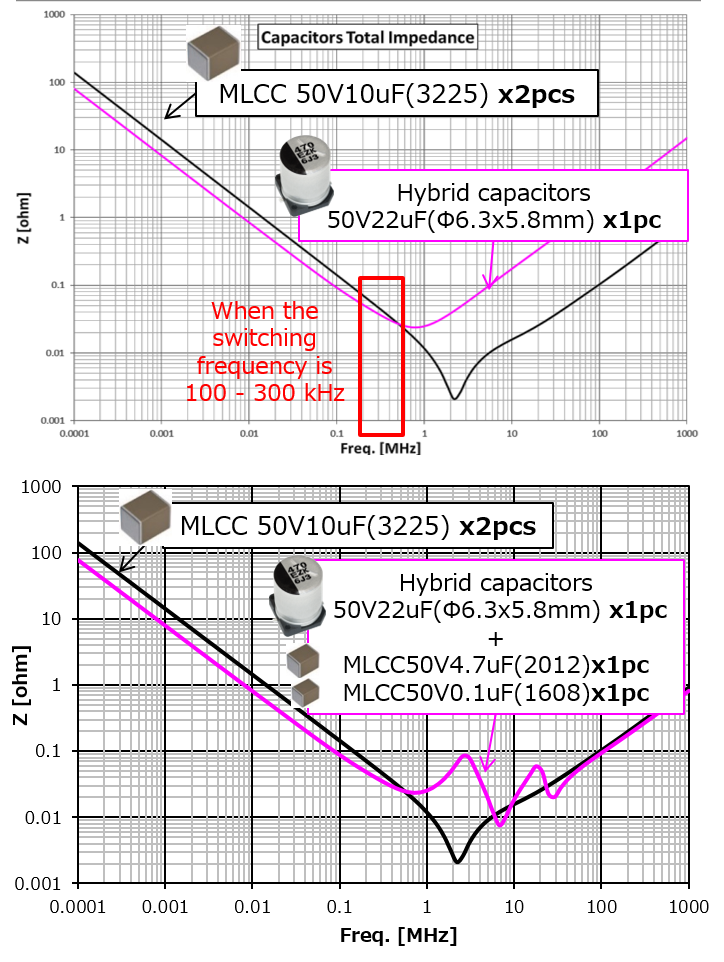
This replacement was possible because, as shown in the frequency characteristic graph at the upper right, the impedance of this hybrid capacitor was equal to or lower than that of the MLCCs at 100 kHz - 300 kHz, which was the switching frequency range of this step-down DC/DC converter.
However, it can be assumed based on the graph that because the impedance of the MLCCs is lower in high-frequency ranges, the high-frequency noise reduction effect is higher. If high-frequency noise actually becomes a problem, then the impedance in high-frequency ranges can be reduced by adding small-capacity general-use MLCCs used for decoupling, etc.
The graph at the lower right shows the frequency characteristics when 0.1 µF and 4.7 µF MLCCs are added to the hybrid capacitor. It indicates the improvement of impedance in high-frequency ranges.
Comparing frequency characteristics:
Hybrid vs. MLCC
Replacing MLCCs Used as Output Capacitors of Switching Power Supply Circuits
The output of switching power supply circuits requires output capacitors (COUT), which, for example, in step-down DC/DC converters, constitute LC filters together with output inductors and smooth the output voltage. Output capacitors repeat the charging and discharging of the triangular ripple current (inductor current) by switching with the output current as the mid-point. To reduce the output ripple voltage of switching power supplies using output capacitors, approaches such as lowering ESR and increasing capacitance are adopted. ESR is an important factor because the output ripple voltage is simply proportional to the ripple current and ESR. In general, MLCCs, aluminum electrolytic capacitors, etc., are used as output capacitors. Although the key features of MLCCs as output capacitors are also their excellent ESR and ESL characteristics, MLCCs can be replaced with hybrid capacitors, as with input capacitors, depending on the frequency characteristics of power supply circuits.
・ Case example of Replacing MLCCs: Isolated Step-down DC/DC Converters for Electric Vehicles (EVs)

This is a case example in which the output capacitors of an isolated step-down DC/DC converter for EVs were replaced from a configuration with MLCCs + aluminum electrolytic capacitors to one with hybrid capacitors. The original output capacitors consisted of forty 25-V, 10-µF (3216 size) MLCCs in parallel and two 25-V, 330-µF (ø10 x 10.2 mm) aluminum electrolytic capacitors in parallel. These could be replaced with twelve 25-V, 330-µF (ø10 x 10.2 mm) hybrid capacitors in parallel.(10×10.2mm)
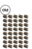
25V10uFx40pcs
(3.2x1.6mm)

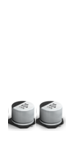
25V330uFx2pcs
(ø10x10.2mm)
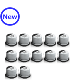
25V330uFx12pcs
(ø10x10.2mm)
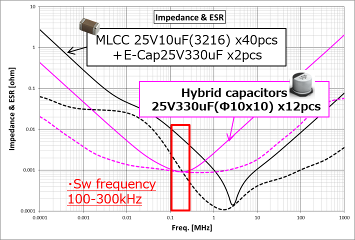
This replacement was possible because the switching frequency range of this isolated step-down DC/DC converter was 100 kHz - 300 kHz, and the ESR and impedance of the configuration with hybrid capacitors in this frequency range were equal to or lower than those of the original configuration with MLCCs + aluminum electrolytic capacitors.
The graph shows the frequency characteristics of the original configuration with MLCCs and aluminum electrolytic capacitors (black) and the replacement configuration with hybrid capacitors (pink). Each solid line shows impedance, and each dotted line ESR characteristics. The configuration with hybrid capacitors is better in terms of the characteristics of both ESR and impedance at 100 kHz - 300 kHz, which is the switching frequency range of DC/DC converters. When high-frequency noise becomes a problem, as mentioned in connection with the replacement of input capacitors, it can be rectified by adding small capacity MLCCs.
Comparing frequency characteristics:
Hybrid vs. MLCC
Summary
This article has introduced case examples of replacing MLCCs, which are used as the input and output capacitors of switching power supply circuits, with hybrid capacitors. In both cases of input and output capacitors, the switching frequency range of power supply circuits was 100 kHz - 300 kHz, and the configuration with hybrid capacitors was able to achieve impedance and ESR values equal to or lower than those of the original configuration with MLCCs. This was the reason that made these replacements possible. Although the noise and EMI requirements of whole power supply circuits need to be met in any case, the possibility of replacing large capacity MLCCs with hybrid capacitors was shown.
Related product information
Tags related to this article
This document summarizes the Basic Knowledge of Capacitors posted as technical information for the Optimal Solutions for Circuit Design.
