High-performance inductors and capacitors incorporated in a filter circuit significantly reduce the size of the circuit and also improve its performance and reliability
2017-09-13
- What advantages do high-performance inductors and capacitors offer?
- What is a metal composite power inductor?
- What is a conductive polymer hybrid aluminum electrolytic capacitor?
- High-performance power inductors and capacitors and their applications
- Related product information
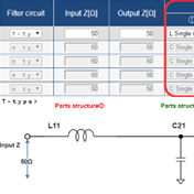
- LC filter simulator
- Tags related to this article
There are various types of inductors and capacitors that vary according to their grade. The past view of these elements was that they were standardized in terms of rating and component size, and so were difficult to differentiate from each other. Today, however, inductors and capacitors show considerably improved performance, thanks to advancements in technology and the development of high-quality materials. High-performance inductors and capacitors are now key items that meet worldwide requirements.
What advantages do high-performance inductors and capacitors offer?
The use of high-performance inductors and capacitors can deliver major advantages. Let's take a look at some working examples before we discuss the specific performance and features of inductors and capacitors.
Working example: an ECU power circuit
This is an example of a power circuit for an in-vehicle ECU. The power circuit shown in this Figure is a basic type that includes not only the ECU but also a DC/DC converter. The power supply line leading from the car battery to the internal circuit of the ECU is provided with an LC circuit, which eliminates noise and controls the operation of the DC/DC converter.
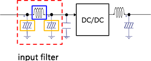
Conventionally, a π-type input filter is composed of a ferrite power inductor and an aluminum electrolytic capacitor. These standard components have been replaced with Panasonic components - a metal composite (hereinafter "MC") power inductor and a conductive polymer hybrid aluminum electrolytic capacitor (hereinafter "hybrid capacitor"). Here is an example of this type of configuration.
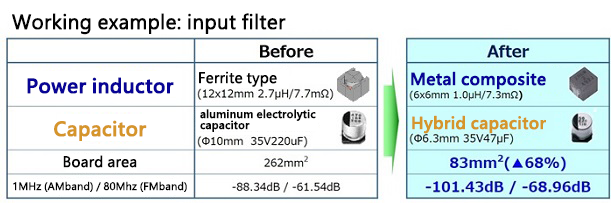
Replacing the ferrite type with the MC type has reduced the footprint of the power inductor from 12×12 mm to 6×6 mm and therefore the area by 75%. Meanwhile, the ø10-mm aluminum electrolytic capacitor has been replaced with a ø6.3-mm hybrid capacitor. As a result, the board area occupied by the input filter has been reduced from 262 mm2 to 83 mm2, that is, cut by 68%.
The high capabilities of the MC power inductor and hybrid capacitor contribute to this dramatic miniaturization of the input filter. The MC power inductor accumulates more energy per unit volume than a ferrite power inductor and has a larger saturation (DC superposition) current. An MC power inductor is smaller than a ferrite power inductor but offers the same performance. In this example, the ferrite power inductor is replaced with an MC power inductor whose area is 1/4 of that of the ferrite power inductor. A hybrid capacitor has vastly lower ESR for its size and capacitance than an electrolytic capacitor and allows a large ripple current flow. The hybrid capacitor is thus smaller in capacitance as well as in size, which is why it has replaced the electrolytic capacitor.
What is a metal composite power inductor?
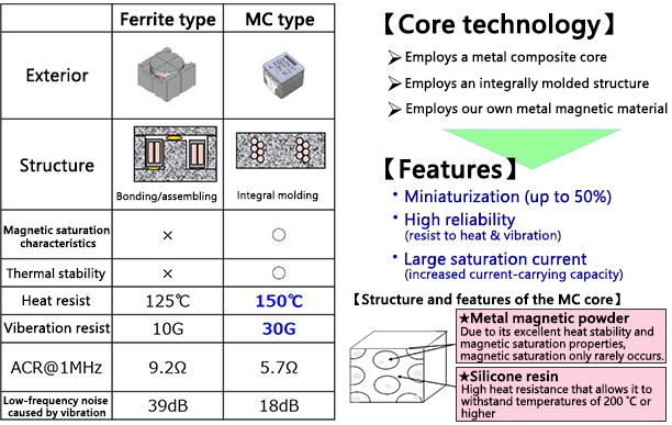
A metal composite (MC) power inductor is different both material-wise and structurally from a ferrite power inductor and has better characteristics than a ferrite power inductor.
The Panasonic MC power inductor has a metal composite core made of an in-house-developed metal magnetic material and an integrally molded structure. This has made it possible to reduce its size up to 50% of that of a ferrite power inductor of the same configuration and to carry a large saturation (DC superposition) current. Due to its low AC resistance (ACR), an MC power inductor is more efficient when operating at high frequencies. It also shows improved heat and vibration resistance, offering high reliability that makes it ideal for use in in-vehicle equipment.
Due to these features, the MC power inductor is used in place of a surface-mounted ferrite power inductor, and is used also as a surface-mounted inductor that replaces a through-hole rod-core-type or toroidal-core-type. At the same time, it achieves a significant reduction in the size and height of the inductor.
What is a conductive polymer hybrid aluminum electrolytic capacitor?
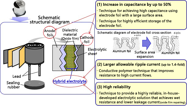
An aluminum electrolytic capacitor is an ordinary capacitor with an electrolytic solution serving as an electrolyte. The conductive polymer hybrid aluminum electrolytic capacitor (hereinafter "hybrid capacitor"), on the other hand, has an electrolyte composed of a mix of a conductive polymer and an electrolytic solution.
The Panasonic hybrid capacitor combines the characteristics of a conductive polymer and those of an electrolytic solution, contributing to miniaturization of in-vehicle equipment and industrial equipment used in harsh environments.
- (1) Increase in capacitance by up to 50%
- (2) Larger allowable ripple current (up to 1.4-fold)
- (3) High reliability
Shown below is a comparison between a hybrid capacitor and an aluminum electrolytic capacitor with the same capacitance and ripple current rating. The sizes and volume indexes of both capacitors indicate that significant miniaturization is possible.
| Aluminum electrolytic capacitor | Hybrid capacitor | |
|---|---|---|
| Same capacitance When the capacitance is 100 µF (35 V): |
Size: ø8×10.2mm Volume index: 100 |
Size: ø6.3×7.7mm Volume index: 47 |
| Same ripple current When the ripple current is 2800 mA rms (25 V): |
Size: ø16×25mm Capacitance: 2200μF Volume index: 100 |
Size: ø10×10.2mm Capacitance: 470μF Volume index: 16 |
Advantages of hybrid capacitors
- The high capacitance of the hybrid capacitor allows it to be smaller in size than an electrolytic capacitor of the same capacitance
- The high ripple current of the hybrid capacitor allows it to be smaller in size than an electrolytic capacitor of the same ripple current.
High-performance power inductors and capacitors and their applications
As described above, we have many examples of miniaturization and performance/reliability improvement achieved by the Panasonic MC power inductor and hybrid capacitor. Their various features mentioned above will now be reviewed and their advantages for use in equipment and circuits and related applications will also be discussed below.
| MC power inductor (MC-PCC) | Hybrid capacitor |
|---|---|
|
|
As mentioned above, these improved inductors and capacitors are ideal for use in industrial fields where smaller and more reliable equipment is needed that is fully operable in demanding environments, such as the automobile, communication base, and industrial equipment fields.
Examples of applications that require components that are smaller in size, larger in current-carrying capacity, and higher in reliability
- In-vehicle ECU
(power pump system input filters, electric fan input filters, engine direct jet input filters, step-up choke coils, brake system input filters, EGR input filters, electric compressor input filters, EPS input filter, S & S step-up/step-down choke coils, I/O filters, body power system input filters, etc.) - Motor control circuit
- DC/DC converter
- Power circuit
Related product information
LC filter simulator
The Industrial & Automotive use LC filter simulator enables the simulation of attenuation amounts when configuring a filter using Panasonic's power inductor and aluminum electrolytic capacitor suitable for industrial & automotive use.
Tags related to this article

This document summarizes the LC filter-related articles posted as technical information for the Optimal Solutions for Circuit Design.
