Topics
- 2019-03-04 "NTC Thermistor (Chip type)" page has been updated.
- 2018-01-09 The part number of Automotive-type has been added (ERTJ0EG202□M).
- 2018-01-19 The part number of Standard-type has been added (ERTJZET154□, ERTJZET224□, ERTJ0ET473□).
- 2016-10-28 Registration certificates of quality and environment certifications (ISO, TS) are available for download
- 2016-07-24 "Cross reference" has been posted
Characteristics of products
Our NTC Thermistors are top-level in the industry and possess following characteristics

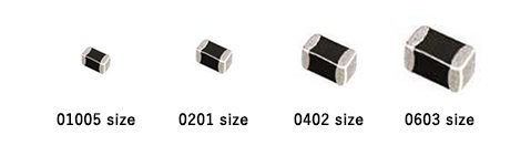
They are surface-mount type products. They are available in a variety of B-values, resistance values and sizes ( 01005・0201・0402・0603 size ) .

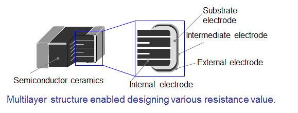
Multilayer structure and our original external electrode forming technology enabled obtaining high-reliability.

We also have automotive components having great heat-resisting properties (up to 150°C)
About NTC Thermistors
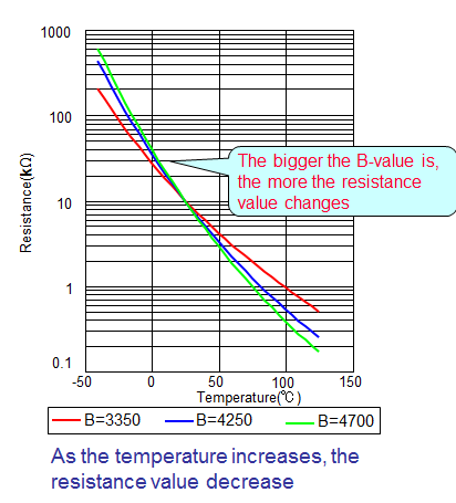
 NTC Thermistor is a ceramic element that changes its resistance value
as the ambient temperature change.
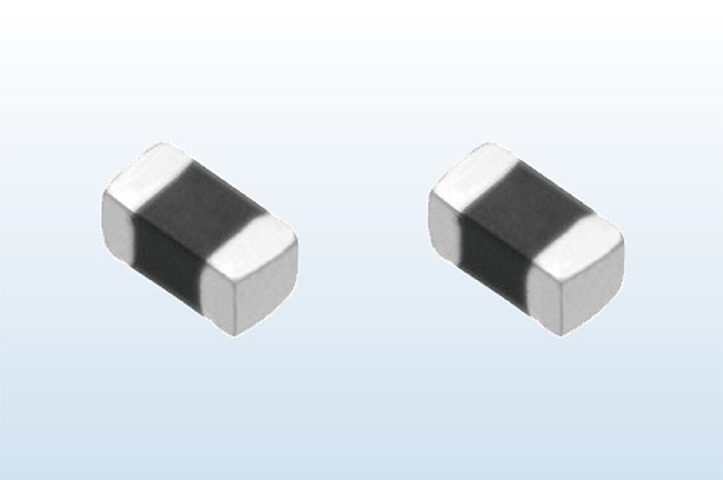
○ Appearance
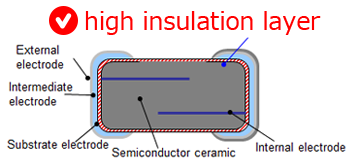
○ Construction
○ Temperature characteristics
Elemental technology
We realized high-reliability by creating high-insulation layer, using our electrode forming technique!
| Conventional technology | Panasonic |
|---|---|

|
 |
| Because of not having high-insulation layer, it is easily affected by external factors : reflow soldering, surrounding environment and atmosphere. | The internal electrodes are protected by high-insulating layer, so it’s not easily affected by external factors : reflow soldering, surrounding environment, and atmosphere. |
〔An image of change in resistance value through the reflow soldering and reliability test〕
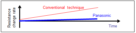
Panasonic’s thermistor maintains temperature control in high precision for a long period.
Items of basic reliability tests
We can conduct additional tests to meet your special demands.
| No. | Items | Testing methods | Perfomance | |||
|---|---|---|---|---|---|---|
| Evaluation items | Standard | High precision | In-vehicle | |||
| 1 | Shock resistance | Shock waveform: Semisinusoidal wave 11ms Impact acceleration : 50G Impact direction : X-X’ ,Y-Y’, Z-Z’(3 times for each direction) |
Change rate of Resistance |
- | - | Within ±2% |
| Change rate of B-value |
- | - | Within ±1% | |||
| 2 | Temperature cycle | -40(in-vehicle:-55)±3°C(30±3min.) →Room temp.(3min. max) →125±3°C(30±3min.) →Room temp.(3min. max) *The operation prescribed above is one cycle, and repeat it for 100 times (in-vehicle components: repeat 2000 times) |
Change rate of Resistance |
Within ±3% | Within ±2% | Within ±2% |
| Change rate of B-value |
Within ±2% | Within ±1% | Within ±1% | |||
| 3 | Moisture resistance | Testing temperature: 85±2°C Relative humidity: 85±5% Testing time:1000+48/0 hours (in-vehicle components :2000+48/0 hours) |
Change rate of Resistance |
Within ±3% | Within ±3% | Within ±2% |
| Change rate of B-value |
Within ±2% | Within ±1% | Within ±1% | |||
| 4 | Damp heat load | Testing temperature: 85±2°C Relative humidity: 85±5% Power applying: 10mW Testing time:1000+48/0 hours (in-vehicle components: 2000+48/0 hours) |
Change rate of Resistance |
Within ±3% | Within ±2% | Within ±2% |
| Change rate of B-value |
Within ±2% | Within ±1% | Within ±1% | |||
| 5 | Low temperature storage |
Testing temperature: -40±3°C Testing time:1000+48/0 hours (in-vehicle components: 2000+48/0 hours) |
Change rate of Resistance |
Within ±3% | Within ±2% | Within ±2% |
| Change rate of B-value |
Within ±2% | Within ±1% | Within ±1% | |||
| 6 | High temperature storage #1 |
Testing temperature: 85±3°C Testing time: 1000+48/0 hours |
Change rate of Resistance |
- | Within ±2% | - |
| Change rate of B-value |
- | Within ±1% | - | |||
| 7 | High temperature storage #2 |
Testing temperature: 125±3°C Testing time: 1000+48/0 hours (in-vehicle component:2000+48/0 hours) |
Change rate of Resistance |
Within ±3% | Within ±2% | Within ±2% |
| Change rate of B-value |
Within ±2% | Within ±1% | Within ±1% | |||
| 8 | High temperature storage #3 |
Testing temperature: 150±3°C Testing time: 1000+48/0 hours |
Change rate of Resistance |
- | - | Within ±3% |
| Change rate of B-value |
- | - | Within ±2% | |||
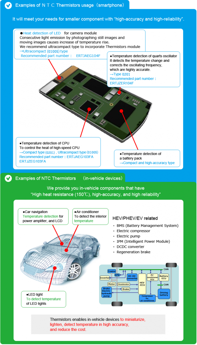
Application