To the top page of use case (SP-Cap, POSCAP, OS-CON)
Requirements for capacitor performance used in Ethernet Switch

Trend of Ethernet Switch
Compact size

Requirement for capacitor performance
Compact size
Large capacity
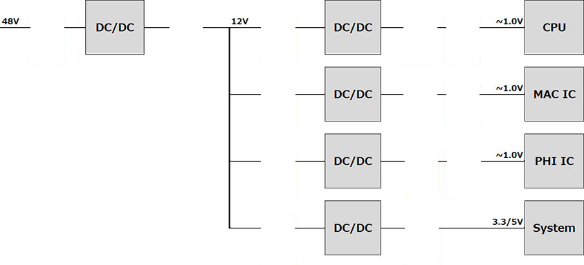
Providing the optimized solution with a high to low voltage power source
Example)
48V system

12V system

5V and lower


 By pressing the button for each circuit block, specific case is shown for reference.
Case 1 - Replacement from MLCC to OS-CON
Introduction of a replacement by using a low ESR capacitor OS-CON SXV series capable of handling high ripple current.
Offered values:
Reduction of quantity and approx. 1/2 the circuit area for handling equivalent ripple current.
saving
reduction
| Before | After | |
|---|---|---|
| Quantity reduction Mounted circuit area image |
 |
 Surface-mounting type  |
| Series, part number | - | SXV series(SMD) 80SXV56M |
| Specifications | 100 V, 15 µF, 5.7 x 5.0 mm | 80 V, 56 µF, ø10 x 12.6 mm |
| Quantity | 9 pcs | 1 pcs |
| Effective electrostatic capacitance | 54 μF 15 μF x 9 pcs x 40 %=54 μF (Capacitance reduced by 48 VDC) |
56 μF (No Capacitance reduced by 48VDC) |
| Mounted circuit area | 286.2 mm2 | 112.4 mm2 |
| Datasheet Specification, part number search |
- | Datasheet Specification, part number search |
Features of OS-CON SXV series
- High voltage resistance: 100V max.
- Ripple current: 3.28A rms max. (105 ℃/100 kHz)
- Low current leakage: 0.05 CV
- High heat resistance: 125 ℃
Case 2 - Replacement from polymer capacitor to OS-CON
Introduction of a replacement by using a low ESR capacitor OS-CON SVPG series capable of handling high ripple current.
Offered values:
Reduction of quantity and approx. 1/2 the circuit area for handling equivalent ripple current
saving
reduction
| Before | After | |
|---|---|---|
| Quantity reduction Mounted circuit area image |
Previous product OS-CON Radial lead type  |
 Surface-mounting type  |
| Series, part number | - | SVPG series 16SVPG330M |
| Specifications | 16 V, 270 µF, ø8 x 9 mm | 16 V, 330 µF, ø6.3 x 10.4 mm |
| Quantity | 3 pcs | 2 pcs |
| Ripple current | 15 A 5.0 A x 3 pcs |
15 A 7.5 A x 2 pcs |
| Mounted circuit area | 150.7 mm2 | 87.1 mm2 |
Features of OS-CON SVPG series, SVPK series
The replacement case shown above uses SVPG series, but high voltage resistance SVPK series can also be used.
| SVPG series | SVPK series | ||
|---|---|---|---|
| Rated voltage | 16 V to 25 V | 16 V to 50 V | |
| Static capacitance | 15 µF to 1,200 μF | 10 µF to 1,200 μF | |
| Features | High ripple current | 7.5A rms max. (105 ℃/100 kHz) (16 V ) |
1.7A rms max. (105 ℃/100 kHz) (16V, 20 V) |
| High capacitance | ~ 1,200 μF | ||
| Compact size | Φ5 x 4.5 mm | Φ5 x 5.9 mm | |
| Low ESR | 6.5 mΩ ~ | 12 mΩ ~ | |
| High voltage resistance | 25 V max. | 50 V max. | |
| Datasheet Specification, part number search |
Datasheet Specification, part number search |
Datasheet Specification, part number search |
|
Case 3 - Replacement from MLCC to SP-Cap (by simulation)
Introduction of a replacement case by using the industry's top-class ultra-low ESR capacitor SP-Cap TZ seriesnoise elimination with an low ESR.
Offered values:
Reduction of quantity with equivalent static effective capacitance, along with noise elimination with an low ESR.。
saving
reduction
| Before | After | ||
|---|---|---|---|
| Quantity reduction Mounted circuit area image |
 |
  |
|
| Series, part number | - | - | TZ series EEFTZ0D561RB |
| Specifications | 4 V, 100 μF, 2.0 x 1.2 mm |
4 V, 47 μF, 2.0 x 1.2 mm |
2V 560uF、7.3 x 4.3 x 2.2mm |
| Quantity | 31 pcs (24 + 7) | 3 pcs | |
| Effective electrostatic capacitance | 1,603 µF (Capacitance reduced by 1.8 VDC) |
1,680 µF (No Capacitance reduced by 1.8 VDC) |
|
| Transient response simulation | 266 mV [P-P] | 266 mV [P-P] | |
| Mounted circuit area | 133.0 mm2 | 132.5 mm2 | |
| Design support tool | - | Simulation data | |
Features of SP-Cap KX series, KZ series, TX series, TZ series
In the case of replacement from the MLCC shown above, the TZ series used, but you can also use the products KX series or KZ series or TX series.
| KX series | KZ series | TX series | TZ series | ||
|---|---|---|---|---|---|
| Rated voltage | 2 to 6.3V | 2V | 2 to 6.3V | 2 V | |
| Static capacitance | 120 to 470 μF | 560 μF | 120 to 470 μF | 560 μF | |
| size | 7.3 x 4.3 x 1.9mm | 7.3 x 4.3 x 2.4mm | 7.3 x 4.3 x 1.9mm | 7.3 x 4.3 x 2.4mm | |
| Features | High capacitance | 470 μF max. | 560 μF max. | 470 μF max. | 560 μF max. |
| Low ESR | 3 to 15 mΩ | 3 to 9 mΩ | 3 to 15 mΩ | 3 to 9 mΩ | |
| Datasheet Specification, part number search |
Datasheet Specification, part number search |
Datasheet Specification, part number search |
Datasheet Specification, part number search |
||
Case 4 - Replacement from MLCC to POSCAP
In the low voltage side, we recommend the compact and large capacity POSCAP TPE series.
Offered values:
Achieving quantity reduction with equivalent capacitance along with compact size and space saving.
saving
reduction
| Before | After | ||
|---|---|---|---|
| Quantity reduction Mounted circuit area image |
 |
  |
|
| Series, part number | - | - | TPE series 2R5TPE1500MC |
| Specifications | 4 V, 100 μF, 2.0 x 1.2 mm |
4 V, 47 μF, 2.0 x 1.2 mm |
2.5 V, 1500 µF, 7.3 x 4.3 mm |
| Quantity | 31 pcs (24 + 7) | 1 pc | |
| Effective electrostatic capacitance | 1,603 µF (Capacitance reduced by 1.8 VDC) |
1,500 µF (No Capacitance reduced by 1.8 VDC) |
|
| Mounted circuit area | 133.0 mm2 | 44.2 mm2 | |
Features of POSCAP TPE series
In the replacement case shown above, TPE series D size product is used, but compact and large capacity TPE series B size product can also be used.
| TPE series | |||
|---|---|---|---|
| TPE series Product dimensions | B size L3.5×W2.8 |
D size L7.3×W4.3 |
|
| Rated voltage | 2.0 V to 10 V | 2.5 V to 10 V | |
| Static capacitance | 47 µF to 470 µF | 68 µF to 1,500 μF | |
| Features | Low profile | 1.9 mm | 1.4 mm |
| Large capacitance | ∼470 µF | ∼1,500 µF | |
| Low ESR | 9 mΩ ~ / 300 kHz(2.5 V) | 7 mΩ ~ (2.5 V) | |
| Datasheet | Specification, part number search |
||
Case 5 - Replacement from MLCC to POSCAP
We recommend the compact and large capacity POSCAP TPE series.
Offered values:
Achieving quantity reduction with equivalent capacitance along with compact size and space saving.
saving
reduction
| Before | After | |
|---|---|---|
| Quantity reduction Mounted circuit area image |
 |
  |
| Series, part number | - | TPE series 6TPE220MAPB |
| Specifications | 6.3 V, 100 µF, 2.0 x 1.2 mm | 6.3 V, 220 µF, 3.5 x 2.8 mm |
| Quantity | 10 pcs | 1 pc |
| Effective electrostatic capacitance | 200 µF 100 μF x 10 pcs x 20% = 200 μF (Capacitance reduced by 5.0 VDC) |
220 μF (No Capacitance reduced by 5.0 VDC) |
| Mounted circuit area | 42.9 mm2 | 16.5 mm2 |
Features of POSCAP TPE series
In the replacement case shown above, TPE series B size product is used, but low profile large capacity TPE series D size product can also be used.
| TPE series | |||
|---|---|---|---|
| Product dimensions | B size L3.5×W2.8 |
D size L7.3×W4.3 |
|
| Rated voltage | 2.0 V to 10 V | 2.5 V to 10 V | |
| Static capacitance | 47 µF to 470 µF | 68 µF to 1,500 μF | |
| Features | Low profile | 1.9 mm | 1.4 mm |
| Large capacitance | ∼470 µF | ∼1,500 µF | |
| Low ESR | 9 mΩ ~ / 300 kHz(2.5 V) | 7 mΩ ~ (2.5 V) | |
| Datasheet | Specification, part number search |
||

