We would like to introduce examples of Panasonic hybrid capacitors adopted by customers.
Component proposal flow
Please give us information on the power circuits and related components you are using.
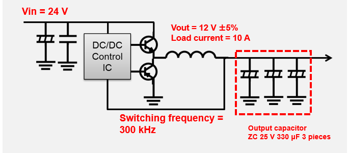
[Power circuit] input voltage, output voltage, load current, switching frequency, etc.
[Components used] power IC, capacitor, inductor, etc.
Based on design information given by the customer, we choose a capacitor that best fits the customer’s product.
Based on the chosen capacitor and information on power elements used by the customer, we conduct a simulation for a circuit in which the capacitor will operate under using service conditions specified by the user.
After analyzing simulation results, we propose an optimum capacitor.
Choose a capacitor as a solution for a problem the customer needs to clear.
- Case 1: Space saving in the board mounting area by reducing the number of output capacitors
- Case 2: Low-height app design achieved by a reduction in the size and height of output capacitors
- Case 3: Space saving in the board mounting area by a reduction in the size of output capacitors
- Case 4: Saving space on the board mounting surface by reducing the number of input capacitors
Case 1: Space saving in the board mounting area by reducing the number of output capacitors
STEP❶ Confirm information on power elements used by the customer.
| Input voltage Vin | 24V |
|---|---|
| Output voltage Vout | 12V |
| Load current | 10A |
| Switching frequency | 300kHz |
| Response to load transient current | |
|---|---|
| Rising | 1A→10A |
| Falling | 10A→1A |
| Through rate | 10A/us |
STEP❷ Choosing a capacitor
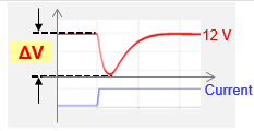
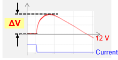
■Comparative evaluation of voltage changes that occur when the capacitor responds to load transient current
<Evaluation results>
| Series | ZC |
|---|---|
| Rated voltage | 25V |
| Capacitance | 330uF |
| Size | φ10x10.2 |
| Ripple current | 2Arms |
| ESR | 20mΩ |
| Number of components | 3 |
| Space | 360 mm2 |
 |
| Total capacitance | 1000uF |
|---|---|
| Size | φ10 or less |
| Total ripple current | 6 Arms |
| Total ESR | 6.7mΩ |
| Number of components | 1 or 2 |
| Space | 240 mm2 |
|
| Series | ZK | ZKU | ZSU |
|---|---|---|---|
| Product number | EEHZK1E471P | EEHZK1E561UP | EEHZS1E102UP |
| Rated voltage | 25V | 25V | 25V |
| Capacitance | 470uF | 560uF | 1000uF |
| Size | φ10x10.2mm | φ10x10.2mm | φ10x16.5mm |
| Number of capacitors (estimate) | 2 | 2 | 1~2 |
| Series | ZC |
|---|---|
| Rated voltage | 25V |
| Capacitance | 330uF |
| Size | φ10x10.2 |
| Ripple current | 2Arms |
| ESR | 20mΩ |
| Number of components | 3 |
| Space | 360 mm2 |
|
| Total capacitance | 1000uF |
|---|---|
| Size | φ10 or less |
| Total ripple current | 6 Arms |
| Total ESR | 6.7mΩ |
| Number of components | 1 or 2 |
| Space | 240 mm2 |
 |
| Series | ZK | ZKU | ZSU |
|---|---|---|---|
| Product number | EEHZK1E471P | EEHZK1E561UP | EEHZS1E102UP |
| Rated voltage | 25V | 25V | 25V |
| Capacitance | 470uF | 560uF | 1000uF |
| Size | φ10x10.2mm | φ10x10.2mm | φ10x16.5mm |
| Number of capacitors (estimate) | 2 | 2 | 1~2 |
STEP❸ Examining the capacitor
| Capacitor Series |
Mounting area Reduction effects |
Rising 1 A → 10 A (spec:△V=600mV) |
Falling 10 A → 1 A (spec:△V=600mV) |
Space saving |
Output voltage Stability |
|||
|---|---|---|---|---|---|---|---|---|
 |
 |
|||||||
|
ZC
25V 330uF
ø10x10.2mm |
 |
224mV | - | 234mV | - | - | - | |
|
ZK
(EEHZK1E471P)
25V 470uF
ø10x10.2mm |
 -33% |
225mV | Equal to the conventional type |
235mV | Equal to the conventional type |
〇 | 〇 | |
|
ZKU
(EEHZK1E561UP)
25V 560uF
ø10x10.2mm |
-33% |
214mV | Improved | 222mV | Improved | 〇 | ◎ | |
|
ZSU
(EEHZS1E102UP)
25V 1000uF
ø10x16.5mm |
 -66% |
222mV | Equal to the conventional type |
234mV | Equal to the conventional type |
◎ | 〇 |  |
| Capacitor Series | Mounting area Reduction effects |
Rising 1 A → 10 A (spec:△V=600mV) |
Falling 10 A → 1 A (spec:△V=600mV) |
||
|---|---|---|---|---|---|
|
|
||||
|
ZC
|
|
224mV | - | 234mV | - |
|
ZK
(EEHZK1E471P)
|
-33% |
225mV | Equal to the conventional type |
235mV | Equal to the conventional type |
|
ZKU
(EEHZK1E561UP)
|
-33% |
214mV | Improved | 222mV | Improved |
|
ZSU
(EEHZS1E102UP)
|
-66% |
222mV | Equal to the conventional type |
234mV | Equal to the conventional type |
| Capacitor Series | Space saving |
Output voltage Stability |
|
|---|---|---|---|
|
ZC
|
- | - | |
|
ZK
(EEHZK1E471P)
|
〇 | 〇 | |
|
ZKU
(EEHZK1E561UP)
|
〇 | ◎ | |
|
ZSU
(EEHZS1E102UP)
|
◎ | 〇 | |
STEP❹ Propose an optimum capacitor
| Product number | Rated voltage (V) | Capacitance (µF) | Rated ripple current (Arms) | Product dimensions (mm) | Durability |
|---|---|---|---|---|---|
| EEHZS1E102UP | 25 | 1000 | 4 (125℃/100kHz) | Φ10×16.5 | 125°C/4000h |
| EEHZS1E102UV (Vibration-resistant product) | 25 | 1000 | 4 (125℃/100kHz) | Φ10×16.8 | 125°C/4000h |
Case 2: Low-height app design achieved by a reduction in the size and height of output capacitors
STEP❶ Confirm information on power elements used by the customer.
| Input voltage Vin | 24V |
|---|---|
| Output voltage Vout | 12V |
| Load current | 10A |
| Switching frequency | 300kHz |
| Response to load transient current | |
|---|---|
| Rising | 1A→10A |
| Falling | 10A→1A |
| Through rate | 10A/us |

STEP❷ Choosing a capacitor
■Comparative evaluation of voltage changes that occur when the capacitor responds to load transient current
<Evaluation results>
| Series | ZC |
|---|---|
| Rated voltage | 25V |
| Capacitance | 330uF |
| Size | φ10x10.2 |
| Ripple current | 2 Arms |
| ESR | 20 mΩ |
| Number of components | 2 |
| Space | 240 mm2 |
|
| Total capacitance | 660uF |
|---|---|
| Size | 8 mm or less in height |
| Total ripple current | 4 Arms |
| Total ESR | 10 mΩ |
| Number of components | - |
| Space | - |
|
| Series | ZK | ZKU |
|---|---|---|
| Product number | EEHZK1E151XP | EEHZKE181XUP |
| Rated voltage | 25V | 25V |
| Capacitance | 150uF | 180uF |
| Size | Ø6.3x7.7 mm | Ø6.3x7.7 mm |
| Number of capacitors (estimate) | 5 | 4 |
STEP❸ Examining the capacitor
| Capacitor Series |
Mounting area Reduction effects |
Rising 1 A → 10 A (spec:△V=600mV) |
Falling 10 A → 1 A (spec:△V=600mV) |
Space saving |
Output voltage Stability |
|||
|---|---|---|---|---|---|---|---|---|
|
|
|||||||
|
ZC
25V 330uF
ø10x10.2mm |
 |
255mV | - | 260mV | - | - | - | |
|
ZK
(EEHZK1E151XP)
25V 150uF
ø6.3x7.7mm |
 +10% |
249mV | Improved | 251mV | Improved | × | 〇 | |
|
ZKU
(EEHZKE181XUP)
25V 180uF
ø6.3x7.7mm |
 -10% |
250mV | Improved | 253mV | Improved | 〇 | 〇 | |
| Capacitor Series | Mounting area Reduction effects |
Rising 1 A → 10 A (spec:△V=600mV) |
Falling 10 A → 1 A (spec:△V=600mV) |
||
|---|---|---|---|---|---|
|
|
||||
|
ZC
|
|
255mV | - | 260mV | - |
|
ZK
(EEHZK1E151XP)
|
+10% |
249mV | Improved | 251mV | Improved |
|
ZKU
(EEHZKE181XUP)
|
-10% |
250mV | Improved | 253mV | Improved |
| Capacitor Series | Space saving |
Output voltage Stability |
|
|---|---|---|---|
|
ZC
|
- | - | |
|
ZK
(EEHZK1E151XP)
|
× | 〇 | |
|
ZKU
(EEHZKE181XUP)
|
〇 | 〇 | |
STEP❹ Propose an optimum capacitor
| Product number | Rated voltage (V) | Capacitance (µF) | Rated ripple current (Arms) | Product dimensions (mm) | Durability |
|---|---|---|---|---|---|
| EEHZKE181XUP | 25 | 180 | 1.8 (125℃/100kHz) | Φ6.3×7.7 | 125°C/4000h |
| EEHZKE181XUV (Vibration-resistant product) | 25 | 180 | 4 (125℃/100kHz) | Φ6.3×7.7 | 125°C/4000h |
Case 3: Space saving in the board mounting area by a reduction in the size of output capacitors
STEP❶ Confirm information on power elements used by the customer.
| Input voltage Vin | 24V |
|---|---|
| Output voltage Vout | 12V |
| Load current | 10A |
| Switching frequency | 300kHz |
| Response to load transient current | |
|---|---|
| Rising | 1A→10A |
| Falling | 10A→1A |
| Through rate | 10A/us |

STEP❷ Choosing a capacitor
■ Comparative evaluation of voltage changes that occur when the capacitor responds to load transient current
<Evaluation results>
| Series | ZC |
|---|---|
| Rated voltage | 25V |
| Capacitance | 330uF |
| Size | φ10x10.2 |
| Ripple current | 2 Arms |
| ESR | 20 mΩ |
| Number of components | 3 |
| Space | 360 mm2 |
|
| Total capacitance | 1000uF |
|---|---|
| Size | φ10 or less |
| Total ripple current | 6 Arms |
| Total ESR | 6.7 mΩ |
| Number of components | 3 |
| Space | 360 mm2or less |
|
| Series | ZKU |
|---|---|
| Product number | EEHZK1E331UP |
| Rated voltage | 25V |
| Capacitance | 330uF |
| Size | ø8x10.2 mm |
| Number of capacitors (estimate) | 3 |
| Series | ZC |
|---|---|
| Capacitance | 25V |
| Capacitance | 330uF |
| Size | φ10x10.2 |
| Ripple current | 2 Arms |
| ESR | 20 mΩ |
| Number of components | 3 |
| Space | 360 mm2 |
|
| Total capacitance | 1000uF |
|---|---|
| Size | φ10 or less |
| Total ripple current | 6 Arms |
| Total ESR | 6.7 mΩ |
| Number of components | 1~2 |
| Space | 240 mm2 |
|
| Series | ZKU |
|---|---|
| Product number | EEHZK1E331UP |
| Rated voltage | 25V |
| Capacitance | 330uF |
| Size | ø8x10.2 mm |
| Number of capacitors (estimate) | 3 |
STEP❸ Examining the capacitor
| Capacitor Series |
Mounting area Reduction effects |
Rising 1 A → 10 A (spec:△V=600mV) |
Falling 10 A → 1 A (spec:△V=600mV) |
Space saving |
Output voltage Stability |
|||
|---|---|---|---|---|---|---|---|---|
|
|
|||||||
|
ZC
25V330uF
ø10x10.2mm |
|
224mV | - | 234mV | - | - | - | |
|
ZKU
(EEHZK1E331UP)
25V 330uF
ø8x10.2mm |
 -25% |
222mV | Equal to the conventional type |
230mV | Equal to the conventional type |
〇 | 〇 | |
| Capacitor Series | Mounting area Reduction effects |
Rising 1 A → 10 A (spec:△V=600mV) |
Falling 10 A → 1 A (spec:△V=600mV) |
||
|---|---|---|---|---|---|
|
|
||||
|
ZC
|
|
224mV | - | 234mV | - |
|
ZKU
(EEHZK1E331UP)
|
-25% |
222mV | Equal to the conventional type |
230mV | Equal to the conventional type |
| Capacitor Series | Space saving |
Output voltage Stability |
|
|---|---|---|---|
|
ZC
|
- | - | |
|
ZKU
(EEHZK1E331UP)
|
〇 | 〇 | |
STEP❹ Propose an optimum capacitor
| Product number | Rated voltage (V) | Capacitance (µF) | Rated ripple current (Arms) | Product dimensions (mm) | Durability |
|---|---|---|---|---|---|
| EEHZK1E331UP | 25 | 330 | 2 (125℃/100kHz) | Φ8×10.2 | 125°C/4000h |
| EEHZK1E331UV (Vibration-resistant product) | 25 | 330 | 4 (125℃/100kHz) | Φ8×10.2 | 125°C/4000h |
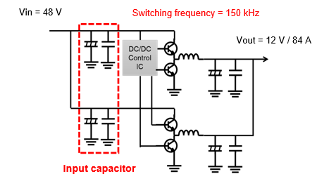
Case 4: Saving space on the board mounting surface by reducing the number of input capacitors
STEP❶ Confirmation of customer information
| Details of the customer's requests | Miniaturize the DC power circuit. ➡ Reduce the number of input capacitors. |
|---|---|
| Customer's problems | ① Selecting a capacitor takes time. ② Connecting capacitors in parallel results in unbalanced ripple current flows in the capacitors. |
| Input voltage Vin | 48V |
|---|---|
| Output voltage Vout | 12V |
| Load current | 84A |
| Switching frequency | 150kHz |
| Incoming ripple current Iripple | Unknown |
| Input capacitor | Hybrid capacitor 63V 180μF capacitor x 8 |
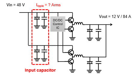
We select an optimum hybrid capacitor and discuss the number of capacitors the customer needs. These capacitors need to meet the customer's requests and solve problems the customer is facing.
- Procedure 1: Based on the customer's circuit conditions and requests, select a replacement series capacitor from products the company offers.
- Procedure 2: Select the optimum replacement series capacitor using a simple circuit simulation and estimate the number of capacitors needed.
- Procedure 3: Taking into account and confirming the influence of unbalanced ripple current through a heat generation simulation, determine the optimum number of capacitors.
STEP❷ Capacitor selection
➡ To achieve a reduction in the number of capacitors, select ZU and ZUU series,, which curb heat generation caused by a large ripple current and are advantageous in terms of capacitance.
| Capacitor selected by the customer | Capacitor initially selected by the company | |||||
| Series | ZSU | ZU | ZUU | |||
| Part number | EHZS1J181UP | EEHZU1J151P | EEHZU1J181P | |||
| Rated capacitance | 63V 180uF | 63V 150uF | 63V 180uF | |||
| Allowable ripple current | 3.5 Arms | 5.2 Arms | 5.5 Arms | |||
| Size | ø10x16.5 | ø10x16.5 | ø10x16.5 | |||
| Number of capacitors | 8 | ー | ー | |||
STEP❸ Examining the capacitor
- Carry out a circuit simulation under the circuit conditions specified by the customer to confirm the ripple current flowing through the input capacitors. → Select the replacement series capacitor.
| Input voltage Vin | 48V |
|---|---|
| Output voltage Vout | 12V |
| Load current | 84A |
| Switching frequency | 150kHz |
| Specifications | Number of capacitors |
On-board mounting image |
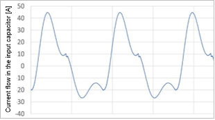
Simulation of a ripple current flow in the input capacitor |
Total ripple current |
Ripple current per capacitor |
Result |
|---|---|---|---|---|---|---|
|
ZSU series
EEHZS1J181UP
63V 180uF Ripple current 3.5Arms ø10x16.5mm |
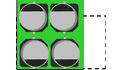
8pcs |  |
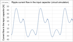 |
23.4 Arms | 2.9 Arms | OK |
| Specifications | Number of capacitors |
On-board mounting image |
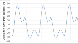
Simulation of a ripple current flow in the input capacitor |
Total ripple current |
Ripple current per capacitor |
Result |
|---|---|---|---|---|---|---|
|
ZU series
EEHZU1J151P
63V 150uF Ripple current 5.2Arms ø10x16.5mm |
6pcs |  |
 |
22.6 Arms | 3.8 Arms | OK |
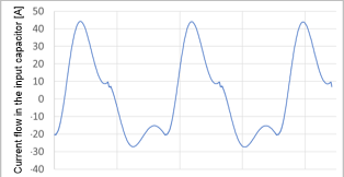
| 4pcs |  |
 |
22.7 Arms | 5.7 Arms | Insufficient (verification required) |
|
|
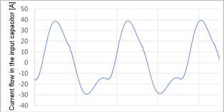
ZUU series
EEHZU1J181UP
63V 180uF Ripple current 5.5Arms ø10x16.5mm | 6pcs | |
 |
22.8 Arms | 3.8 Arms | OK |
| 4pcs | |
 |
23.1 Arms | 5.8 Arms | Insufficient (verification required) |
| Verification item | Conclusion |
|---|---|
| Ripple current | Both ZU series and ZUU series can be used in a set of 6 capacitors if the unbalanced ripple current is not to be taken into consideration. ➡Find the optimum number of capacitors, including when there are only 4 capacitors, by carrying out a detailed heat generation simulation. |
| Capacitance | Comparing the ZU series (150 uF) and ZUU series (180 uF) finds no significant difference in capacitance between both products. ➡Adopt the ZU series. |
- Unbalance of ripple currents applied respectively to capacitors caused by variations in wiring configurations on the board
- Influence of a heat-generating device near the input capacitor
Check the self-heat generation of the hybrid capacitor carrying the maximum ripple current flow and determine whether or not to use the capacitor.
| Specifications | Number of capacitors |
Heat generation simulation (temperature rise at the heat-generating capacitor) |
Determination on heat generation |
|---|---|---|---|
|
ZSU series
EEHZS1J181UP
63V 180uF ø10x16.5mm |
8pcs | 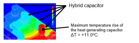 |
OK Within the heat generation tolerance |
|
ZU series
EEHZU1J151P
63V 150uF ø10x16.5mm |
6pcs | 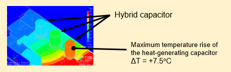 |
OK Within the heat generation tolerance |
| 4pcs | 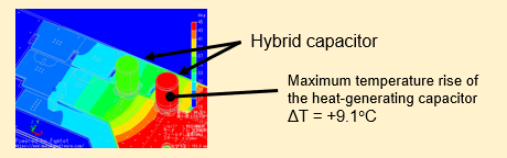 |
OK Within the heat generation tolerance |
STEP❹ Propose an optimum capacitor
| Capacitor selected by the customer | Capacitor initially selected by the company | |||||
| Series | ZSU | | ZU | |||
| Part number | EHZS1J181UP | EEHZU1J151P | ||||
| Rated capacitance | 63V 180uF | 63V 150uF | ||||
| Allowable ripple current | 3.5 Arms | 5.2 Arms | ||||
| Size | ø10x16.5 mm | ø10x16.5 mm | ||||
| Number of capacitors | 8pcs | 4pcs | ||||
| Mounting area ratio | 1 | 50% reduction |  | |||
| Part number | Rated voltage (V) | Capacitance (µF) | Rated ripple current (Arms) | Product size (mm) | Durability |
|---|---|---|---|---|---|
| EEHZU1J151P | 63 | 150 | 5.2 (125℃/100kHz) | Φ10×16.5 | 125°C/4000h |
| EEHZU1J151V (vibration-resistant product) | 63 | 150 | 5.2 (125℃/100kHz) | Φ10×16.8 | 125°C/4000h |
- EPS carrying a large current flow
- Cooling fan, etc.