Chip resistor's failure phenomenon/mechanism and solutions (2)
2021-10-25
In the previous article, in addition to "Outline of failure phenomena," we also explained, "Migration," "Electrolytic corrosion," and "Sulfurization" listed below. [Click here to see the previous article.]
This article will explain the other four items, including "Electrode separation" and "Resistive element deterioration."
| No. | Failure phenomenon | Usage Environment | Failure position | Applicable chip Resistor type |
Failure mode |
|---|---|---|---|---|---|
| 1 | Migration | Halogen composition attachment | Internal electrode | All | Resistance value reduction, shorted circuit |
| 2 | Electrolytic Corrosion | Resistive element | Thin film type | Resistance value increase, open circuit (wire breakage) | |
| Environment containing sulfur | Resistive element | Thin film type | |||
| 3 | Sulfurization | Internal electrode | All | ||
| 4 | Electrode separation | Excessive mechanical stress | Intermediate electrode | All | |
| 5 | Solder Crack | The solder used for circuit mounting | All | ||
| 6 | Resistive element burnout | Electrical overload | Resistive element | ||
| 7 | Resistive Element Deterioration | Resistive element | Thick film type | Resistance value reduction |
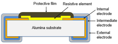
Electrode separation
Electrode separation refers to a fault case where strong stress applied to a chip resistor causes the inner electrode to separate from the intermediate electrode.
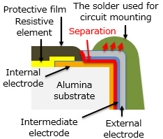
The mechanism by which electrode separation occurs
A reflow process involves solder shrinking excessively, the printed board's bending, or the molding resin setting/shrinking. These phenomena create strong stress applied to the intermediate electrode, causing it to separate from the inner electrode. This increases the resistance value and ultimately leads to an open circuit failure (wire-breaking). This failure occurs when too much solder is used, or the chip resistor is mounted under reflow conditions not conforming to recommended reflow conditions. In addition, using a special solder type that suppresses crack formation, such as high-temperature solder, may also cause electrode separation. Incidentally, the molding resin setting/shrinking leads not only to cracking of the terminal but also to cracking of the chip itself.
Solutions to prevent electrode separation
Preventing electrode separation requires using a proper amount of solder and chip mounting under conditions conforming to recommended reflow conditions.
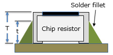
The following are criteria for determining the proper amount of solder.
T ≧ t ≧ T/3
T: chip resistor height
t: solder filet height
Recommended reflow conditions for our products are included in the product specifications available to the public. Please check the product specifications.
Solder Crack
Solder cracking can be caused by thermal shock stress created in a customer's service environment.
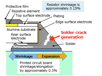
The mechanism by which solder cracking occurs
Cycles of temperature changes (temperature cycles) repeated in a service environment may cause the chip resistor and the printed board to thermally expand and shrink at respective expansion/shrinkage rates different from each other. This creates stress that may cause the solder to crack. This is a problem that often occurs in applications involving large temperature differences, such as using the chip resistor as an automotive component, thus it requires special caution to implement. Solder cracking increases the resistance value, leading to an open-circuit failure (wire-breaking) in the end.
A solution to prevent solder cracking
To alleviate the effects of temperature changes (temperature cycles) repeated in a service environment, it is important to use the proper amount of solder and select appropriate materials (PCB, solder). In addition, adopting components highly resistant to thermal shocks (a downsized component, a resistance with elongated electrodes, etc.) are also effective for reducing temperature cycle effects.
Our company adopts a soft electrode material to improve the product's resistance to stress, thereby suppressing crack development. We have a "highly heat-resistant chip resistor" on our product lineup. This product has achieved guaranteed performance for 1000 temperature change cycles in a -55°C/+175°C thermal shock test*.
*The product achieves its guaranteed performance for 1000 temperature change cycles in a -55°C/+175°C thermal shock test* when mounted under the recommended usage conditions for the solder, board, land, etc. For detailed information about this, please check the product specifications.
Resistive element burnout
Resistive element burnout occurs when a resistive element is exposed to an excessive load, ESD, surge pulse, etc.
The mechanism by which resistive element burnout occurs
An excessive load, ESD, surge pulse, etc., causes a large current to flow instantaneously through the resistive element, generating heat as a consequence. This damages the resistive element, increasing its resistance or, worst case, leading to breaking the circuit (open circuit failure).
A solution to prevent resistive element burnout
The rated power is specified for the chip resistor, and using the chip resistor with power equal to or lower than the rated power is a basic requirement. So design the circuit where the chip resistor is supplied with power equal to or lower than the rated power. It is difficult, however, to keep an instantaneous power load, such as electrostatic discharge (ESD) and surge (on-off surge), equal to or lower than the rated power, so the following two measures to deal with a chip resistor exposed to ESD or surge should be taken.
- (1) Provide the circuit with anti-ESD/surge components to minimize the overall effects of ESD/surge on the circuit (use an ESD suppressor, varistor, etc.)
- (2) Select a component highly resistant to ESD/surge.
Our product lineup has a "highly resistant/highly reliable thin-film chip resistor" and a "small-sized high-power chip resistor." These chip resistors show high resistance to ESD/surge.
Resistive Element Deterioration
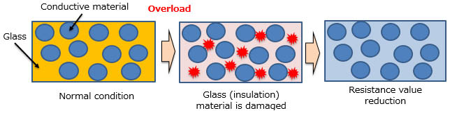
Resistive element deterioration refers to a case where an overloaded resistive element generates heat and deteriorates by heat generation. This problem often occurs with a thick-film chip resistor made with materials such as conductive particles and glass.
The mechanism by which resistive element deterioration occurs
When an excess load (such as excess current, ESD, and surge) is applied to a thick-film chip resistor for a very short period, it does not result in melting of the resistive element of the resistor, but it drops the insulating properties of glass (insulator) that makes up the resistive element and reduces the resistance of the chip in some cases.
A solution to prevent resistive element deterioration
The method for preventing resistive element deterioration is basically the same as preventing resistive element burnout. However, because resistive element deterioration is a problem characteristic of the thick-film chip resistor, we offer a "small-sized high-power chip resistor," a thick-film chip resistor highly resistant to ESD/surge, as a solution to this problem.
Related information
Related product information
Tags related to this article

This document summarizes the Chip resistor’s failure phenomenon/mechanism and solutions posted as technical information for the Optimal Solutions for Circuit Design.
