Current Detection Chip Resistors for Responding to the Large Current and High Precision Requirements
2017-11-20
Many types of resistors are available with characteristics, performance and shapes for meeting different applications and operating environmental conditions. In recent years, to meet the basic requirement for compact size and lightweight, chip resistors have been become main stream particularly in electronic equipment. In addition, the increasing requirement of battery operated equipment to save energy, and ensuring safety and comfort have been important issues, so “current detection resistors (shunt resistors)” used for battery management and power system control as well as protection have been getting attention.
What are current detection resistors (shunt resistors)?
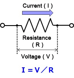
Current detection resistor is a common name for resistors inserted in series of a current's path and measuring the current value of the voltage drop generated through Ohm's law. As a high resistance value generates a large voltage drop and increases heat generation as well as loss, a resistor with a low resistance value of 1 Ω or below is generally used.
Originally, the name, shunt resistor, was used for a resistor connected in parallel with an ammeter for the purpose of a current divider and expanding the range of the ammeter measurement by using the resistance ratio of the current divider and ammeter. However, in recent years, a resistor used for current detection described above is also called a shunt resistor and not clearly distinguished from the original purpose.
Because this article describes the application for measuring current by inserting a resistor in series, such a resistor is called a current detection resistor. Even if the name is different by application, the same resistor can be used for both purposes as long as the required specification is the same and no clear distinction exists for the characteristics and structure of the resistor.
Applications of Current Detection Resistor
In electronic equipment, detecting current in the circuit and controlling it is very important for achieving higher performance, improved safety and better energy consumption. A current detection resistor is a component used for converting circuit current to voltage with a minimum loss of power. Among the variety of applications, three types of the principal use are shown below.
Excess Current Detection
When an abnormal large amount of current flows through a circuit due to a failure or overload, current detection is required for actions such as stopping the circuit operation.
Examples of excess current detection applications
- Excess current protection in a power circuit
- Over discharge and overcharge protection of a rechargeable battery
- Excess current protection of a motor
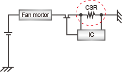
※CSR:Current Sensing Resistor: Current Detection Resistor
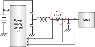
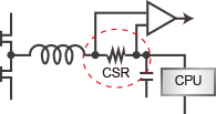
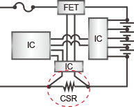
Current Control
Peak current detection of an inductor for controlling the maximum output current of a DC/DC converter, current detection for phase and time control for driving a 3-phase motor, etc.
Examples of current control applications
- DC-DC converter
- Inverter power supply
- AC motor current control
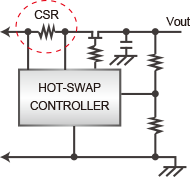
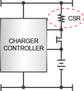
Current Management
Example of current management applications
- Current management of rechargeable battery-driven equipment such as a notebook PC and mobile phone
- Current management of rechargeable batteries in a hybrid automobile
Performance requirements for current detection resistors and Panasonic's activities
With the recent advancement toward higher functionality of electronic equipment, current volume in the circuit increases and resistors capable of handling higher power are required. In addition, the requirement of low resistance for suppressing power consumption in a circuit, and for high accuracy resistors for providing good resistance temperature coefficient in a severe temperature environment is increasing.
For example, in the case of charging a smart phone, the maximum charge current used to be 0.5 A, but in response to rapid charging, the current rating was increased to a Max of 5 A for charging with a new method USD PD.
Also, equipment power consumption is in an increasing trend of low voltage with large current, and current consumption is increasing.
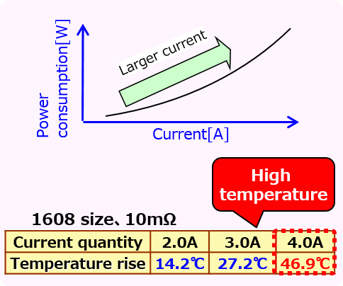
With this large current operation, the current that is detected by the current detection resistor, that is, the current that flows through the current detection resistor is increasing. As is obvious, the greater the current in the resistor, the larger the heat generation caused by loss (I2R). Heat generation of a resistor also causes a change to its resistance value and affects reliability. It also causes ambient temperature rise and leads to a problem of the entire equipment.
At Panasonic, we are developing current detection chip resistors in response to the heat generation caused by a larger current consumption in electronic equipment. For suppressing heat generation and loss, we promote “lower resistance”. In addition, for maintaining the change of the resistance value to the minimum through temperature changes, we are “improving temperature coefficient (TCR)”.
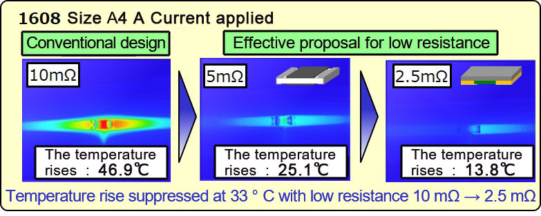
Lower resistance
As described above, heat generation of a resistor depends on loss (I2R). Therefore, heat generation can be reduced by reducing resistance value. The diagram shown to the bottom indicates the difference in heat generation by resistance value when a current of 4 A is applied. As an example, by reducing the 10 10mΩ resistance value of a resistor to 2.5 mΩ, heat generation can be reduced by 33℃.
Panasonic has proposed to reduce heat generation of a resistor by developing a current detection chip resistor with a lower resistance value and using it. The specific measures are as follows.
- <Thick film type>
- ・ Structure of using resistance film on both sides of a substrate and making the product shape rectangular to achieve lower resistance.
- ・ Changing the resistance material from AgPd to a lower specific resistance value material CuNi.
- <Metal plate type>
- ・ From the structure of printing resistance paste on a substrate to a newly developed structure of using a metal plate/foil as a resistance element. The new structure enables a thicker resistance element for covering a resistance rage of 5mΩ or below. Not achievable by using the printed structure.
Improvement of Temperature Coefficient (TDR)
Accurate current measurement can be achieved by using a resistor with a smaller temperature coefficient because such resistors can maintain a small change of resistance value when temperature changes. For example, a smaller temperature coefficient reduces the error in the remaining battery charge of portable equipment, and enables extended operation with accurate control and management.
However, “lower resistance” and “lower temperature coefficient” are in a contradicting relationship, and reduced resistance presented the problem of increased temperature coefficient which reduced accuracy.
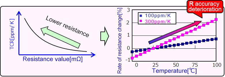
Panasonic solved the problem by improving the material in the resistance element and electrode, and then commercialized current detection chip resistors with low resistance and low temperature coefficient.
Tips for Using Current Detection Resistors
Current detection is based on Ohm's law by measuring the voltage across a resistor generated by the current, and using the equation, Current = Voltage ÷ Resistance value. Therefore, the detected voltage, and current - voltage conversion gain, is determined by the value of the current detection resistor. The converted voltage needs the voltage value to be easily controlled in the circuit. By including these points, tips for using typical current detection resistors are summarized below.
Selection of Resistance Value
Smaller resistance value of a current detection resistor is desirable for reducing loss (I2R), but for the purpose of reducing impacts such as noise, resistance value needs to be higher for increasing the detected voltage. Resistance value of a current detection resistor needs to be determined by finding a compromising point in these contradicting requirements.
Selection of Rated Power
When selecting a rated power of a current detection resistor, rush current needs to be taken into consideration in addition to the maximum current in a steady condition. Exceeding the rated power may cause a failure of the resistor due to heat generation.
Selection of Temperature Coefficient (TCR)
Changes in resistance value of a current detection resistor caused by heat generation due to loss (I2R) and changes of ambient temperature generate current detection errors. Therefore, a product with a temperature coefficient (TCR) that can satisfy the required accuracy of the measured value needs to be selected.
Wiring for Voltage Detection
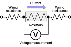 When connecting wires to detect the voltage at both ends of a current detection resistor on a circuit board, use caution not to include the wire of a resistor inserted in series by selecting the closest two pins of the resistor. Copper foil resistance of wiring is said to be approx. 5mΩ/1 cm (35 µm thick, 1 mm wide), while the resistance value of a current detection resistor is generally several-10 to several-100 mΩ, meaning the addition of copper foil resistance will generate a large error. In this case, use of a Kelvin connection is useful.
Related product information
Tags related to this article

This document summarizes the Chip resistors related articles posted as technical information for the Optimal Solutions for Circuit Design.
