Fundamentals of Capacitors and Hybrid Capacitors
2017-12-18
Fundamentals of Capacitors
Capacitors are one of the three major passive components, along with resistors and coils. Capacitors are simple components, but almost no electric/electronic circuits are without capacitors. There is no way that the circuits of advanced devices such as PCs and smartphones can work without capacitors. Besides, capacitors are one of the most important components for CPUs and communication chips, which are core parts of these devices.
What are capacitors?
Capacitors are electronic components that can store a charge on the surface of their internal electrodes. They store a smaller charge than batteries and therefore can supply current for only a short period of time. However, they can be used repeatedly and can provide a large current instantaneously.
An insulator (Dielectric) sandwiched between metal plates (Electrodes) in parallel makes up a capacitor. Applying DC voltage across the metal plates (Electrodes) enables it to store a charge. This is the principle of capacitors. The amount of charge that can be stored is referred to as capacitance, and capacitance ‘C’ is determined by permittivity ‘ε’ of the insulator, surface area ‘S’ of the electrodes, and thickness ‘d’ of the insulator.
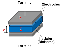
S
d
- C
- Capacitance
- ε
- Permittivity of the insulator
- S
- Electrode surface area
- d
- Thickness of the insulator
Capacitors are electronic components that can store a charge on the surface of their internal electrodes. They store a smaller charge than batteries and therefore can supply current for only a short period of time. However, they can be used repeatedly and can provide a large current instantaneously.
Functions of capacitors
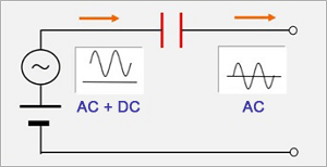
Capacitors have and provide the following properties in electric circuits:(1) Capable of instantaneous charge and discharge; (2) Do not pass DC but pass AC; and (3) Pass AC more easily at higher frequencies.
Here are circuit examples for typical use of capacitors.
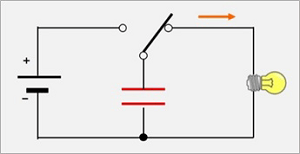
Discharge circuits
Discharge circuits operate loads connected to them by discharging charge stored in capacitors. They are used in strobe lights for cameras, emergency backup power supplies, etc., since they can discharge large current instantaneously.
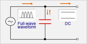
Smoothing circuits
Smoothing circuits convert AC to DC. They are used to suppress fluctuation ranges of waveforms that have undergone full-wave rectification by bridge circuits of power supplies, etc.
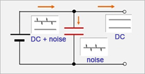
Decoupling circuits
Decoupling circuits, as their name suggests, are used to prevent the propagation of fluctuation (Noise) that occurred in the previous stage and carried over to the subsequent stage. One example of such use is removing the switching noises of switching power supplies.
Coupling circuits
Coupling circuits, conversely, extract only changed portions (AC components) from the signal of the previous circuit and propagate it to the latter circuit. They are used in audio signal circuits, etc.
Characteristics of capacitors
Ideal capacitors consist only of capacitance components. However, actual capacitors include resistance and inductance components. These parasitic components significantly affect the performance of capacitors. The diagram below shows the simplified equivalent circuits of capacitors. As shown in the diagram, an equivalent circuit of an actual capacitor includes ESR (equivalent series resistance) and ESL (equivalent series inductance). In addition, ideally, there should be insulation between the electrodes of a capacitor. However, in fact some leakage current exists.
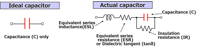
These components are summarized below.
| Characteristic items | Explanation |
|---|---|
| Capacitance (C) |
|
| Equivalent series resistance (ESR) Dielectric tangent (tanδ) |
|
| Insulation resistance (IR) |
|
| Equivalent series inductance (ESL) |
|
Another important characteristic is impedance.
In short, impedance is a voltage to current ratio in AC circuits and equivalent to a resistance in DC currents. Its symbol is Z, and is expressed using Ω, as with resistance.
- Impedance (Z) of capacitors is expressed by the following equation.
- Z = R + j 2πf L+ 1/(j 2πf C)
- The absolute value of impedance is calculated by the following equation.
- |Z| =√R2+(2πf L - 1/(2πf C))2
- Z
- Impedance [Ω]
- R
- Resistance component =ESR [Ω]
- j
- Imaginary number
- π
- Pi (3.14)
- f
- Frequency [Hz]
- L
- Inductance component =ESL [H]
- C
- Capacitance [F]
This equation indicates the following.
- Impedance is determined mostly by capacitance (C) in low-frequency ranges.
- Impedance is determined by ESR at self-resonant frequencies
(Frequencies with 2πf L = 1/(2πf C)). - Impedance is determined mostly by ESL in high-frequency ranges.
The graph below shows these.
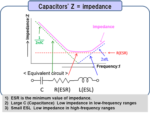
The impedance Z of capacitors is capacitive (C) and decreases up to the self-resonant frequency. However, at the self-resonant frequency, the effect of C and ESL become zero, and the impedance consists only of ESR. After this point, the impedance becomes inductive (ESL) and increases with the frequency.
When using capacitors for noise absorption (Decoupling), one of its major applications, the following points need to be taken into consideration when selecting components since noise absorbing effects are determined by impedance.
- Noise frequencies and the self-resonant frequency of the capacitor are close.
- Small ESR
- Small ESL in the case of high-frequency noises
Types of capacitors and their features
There are a variety of capacitors depending on the materials used, structures, etc. In addition, their features differ by type. Design selection is based on these features.
| Items | ※Multilayer ceramic |
Film | Aluminum electrolyte |
Tantalum electrolyte |
Conductive polymer |
Electric double layer |
|---|---|---|---|---|---|---|
| Large capacity | △ | × | 〇 | 〇 | △ | ◎ |
| High voltage compatibility |
〇 | ◎ | 〇 | △ | △ | × |
| Long life | ◎ | ◎ | △ | 〇 | 〇 | △ |
| Temperature characteristics |
△ | ◎ | △ | 〇 | ◎ | △ |
| Low ESR | ◎ | ◎ | × | △ | 〇 | × |
| Polarity | No | No | Yes | Yes | Yes | Yes |
| Other | The capacity caused by DC bias varies greatly | High precision High price |
Low price No small products | If a fault occurs, it tends to ignite | ||
| Major applications |
|
|
|
|
|
|
※The laminated ceramic is a characteristic of a high dielectric constant laminated ceramic capacitor.
In addition, conductive polymer hybrid aluminum electrolytic capacitors, which integrate aluminum electrolytic capacitors and conductive polymer electrolytic capacitors, combines the features of both, and have been attracting attention in recent years.
Conductive Polymer Hybrid Aluminum Electrolytic Capacitors
Conductive polymer hybrid aluminum electrolytic capacitors, with the electrolyte fused with conductive polymer and electrolyte liquid, are suitable for automotive equipment, communication base stations, etc. which need compact and highly reliable components.
Aluminum electrolytic capacitors
Conductive polymer hybrid aluminum electrolytic capacitors are, as their name indicates, part of the aluminum electrolytic capacitors. For a better understanding of conductive polymer hybrid aluminum electrolytic capacitors, we'll first give a brief explanation of aluminum electrolytic capacitors.
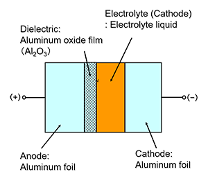
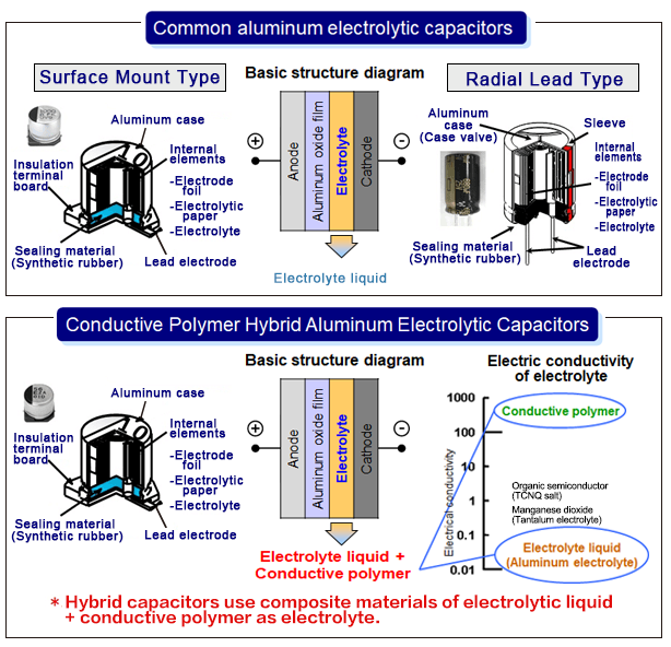
Aluminum electrolytic capacitors have a structure, in which an oxide film, which becomes an insulator (Dielectric), is formed on the surface of the aluminum foil of the anode, and electrolyte liquid (liquid consisting of a solvent in which electrolyte is dissolved) is used as electrolyte (Cathode).
One feature of aluminum electrolytic capacitors is a large capacity, and this is achieved by increasing electrode surface area (S) through the etching of the of aluminum foil surface to form irregularities and by forming ultra-thin thickness (d) of oxide films at the Angstrom level.

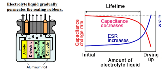
Aluminum electrolytic capacitors are products with limited life. The electrolyte liquid vaporizes depending on the temperature and gradually penetrates sealing rubber. Consequently, the capacity decreases and ESR rises over time, and it will become an open state (Electrolyte liquid having dried up) in the end.
When estimating the life of aluminum electrolytic capacitors, "10℃ 2-fold law" can usually be applied.
What are conductive polymer hybrid aluminum electrolytic capacitors?
Conductive polymer hybrid aluminum electrolytic capacitors ("hybrid capacitors") adopt hybrid electrolyte fused with conductive polymer and electrolyte liquid and show excellent performance with the advantages of both conductive polymer electrolytic capacitors and aluminum electrolytic capacitors. Compact yet achieving high breakdown voltage, large capacity, low ESR, large ripple current, and long life. It should be noted that the final failure mode is open mode, the same as that of aluminum electrolytic capacitors, and the "10º℃ 2-fold law" applies to its life estimation equation.
The basic structures of common aluminum electrolytic capacitors and hybrid capacitors are compared below. Both basically have the same structure, but are different in electrolyte, as described earlier.
Features of hybrid capacitors
The most significant feature of hybrid capacitors is their capability to pass large ripple current at low ESR compared to conventional aluminum electrolytic capacitors.
Low ESR reduces energy losses due to ESR in addition to achieving large noise-absorbing effects, and furthermore, self-temperature rise due to the energy losses will be smaller.
Smaller self-temperature rise will extend the life of capacitors, and assuming that they have the same life, those with low ESR can be regarded as capable of passing larger current.
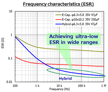
The graph on the right compares ESR frequency characteristics of aluminum electrolytic capacitors and hybrid capacitors.
Usually, the larger the capacity of aluminum electrolytic capacitors, the larger their size and the lower their ESR. However, compared with aluminum electrolytic capacitors, hybrid capacitors, which feature low ESR, can obtain equivalent ESR values with smaller capacity and smaller size.
Hybrid capacitors with 47 μF have lower ESR than aluminum electrolytic capacitors with 330 μF.
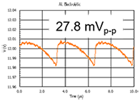
As an example, we compare the use of a 330 μF aluminum electrolytic capacitor and of a 47 μF hybrid capacitor for smoothing the output of switching power supplies. As shown below, using a 47 μF hybrid capacitor can lower the output ripple voltage.
In addition, the size can be significantly downsized from ø10 × 10.2 mm to ø6.3 × 5.8 mm.
| Aluminum Electrolytic Capacitors | Hybrid Capacitors | |
|---|---|---|
| size | (G) ø10.0X10.2 mm | (D) ø6.3X5.8 mm |
| Capacitance | 330 μF | 47 μF |
600mVp-p+DC12V 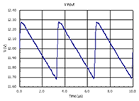 |
 |
 |
| Mounting area ratio | 100 % (132 mm2) | 41 % (54 mm2) |

Application examples of hybrid capacitors
As described earlier, hybrid capacitors have improved the weak points of conventional aluminum electrolytic capacitors such as low-temperature characteristics, ESR characteristics, and high ripple through the adoption of a conductive polymer while keeping their advantages (safety, low LC). Taking advantages of these features, more hybrid capacitors are adopted for applications that require safety and reliability, such as automotive and industrial equipment.
Lastly, we introduce examples of reducing the number of components and downsizing through the adoption of hybrid capacitors.
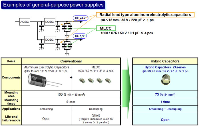
In the first example, output capacitors for general-purpose power supplies replaced the radial lead type 220 μF aluminum electrolytic capacitor × 1 + MLCC × 5 with a single 47 μF hybrid capacitor. The hybrid capacitor is a surface mount type. In addition to reducing the number of components and mounting area and achieving full surface mounting, reliability is improved by not using MLCC in short-circuit failure mode.
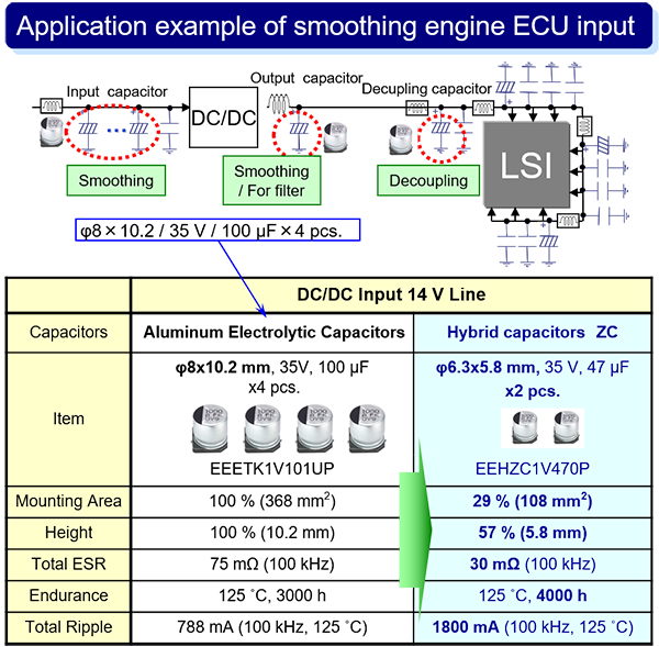
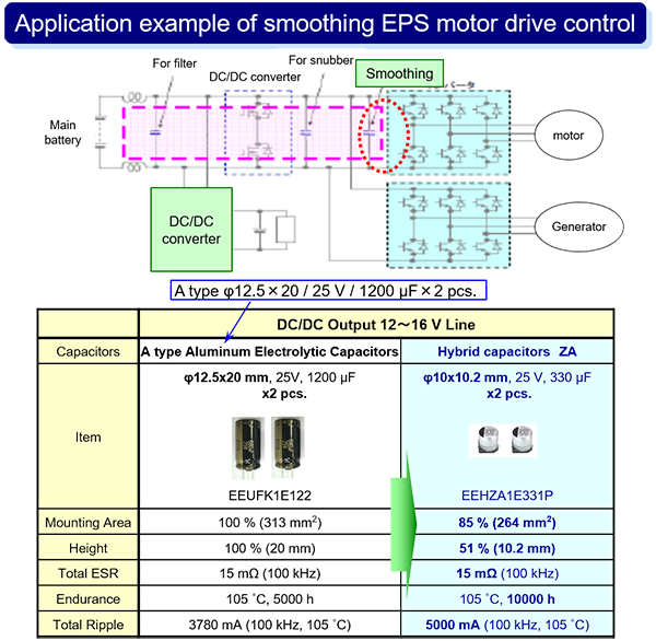
Next, we will introduce the examples of engine ECU and EPS motor control circuit power supplies. In the example of engine ECU, aluminum electrolytic capacitors used for DC-DC converter input were replaced by hybrid capacitors. The number of components was halved, and the mounting area was also significantly reduced. In the example of EPS motor control, radial lead type capacitors used for smoothing were replaced by surface mount type capacitors. The mounting area and height were reduced, while reliability and ripple current rating improved.
These examples show the significant advantages of hybrid capacitors.
Related product information
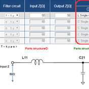
LC filter simulator
The Industrial & Automotive use LC filter simulator enables the simulation of attenuation amounts when configuring a filter using Panasonic's power inductor and aluminum electrolytic capacitor suitable for industrial & automotive use.
Tags related to this article

This document summarizes the LC filter-related articles posted as technical information for the Optimal Solutions for Circuit Design.
