Basic Knowledge of Inductors (1)
-Basic Structure, Symbols, Voltage and Current-
2018-09-03
What Are Inductors?
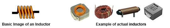
Inductors, also referred to as coils, are important passive components along with resistors (R) and capacitors (C). Coils usually refer to wound conductive wires, and among them, those with a single wound wire have in recent years particularly been referred to as inductors.
Inductance is usually represented by the symbol "L." Although this L is said to come from Lenz of "Lenz's Law" related to electromagnetic induction, there also appear to be various theories.
The basic structure of an inductor consists of a conductive wire wound in a coil shape and is able to convert electric energy to magnetic energy and store it inside the inductor. The storable amount of magnetic energy is determined by the inductance of the inductor and measured in Henry (H).
Basic Structure of Inductors and Inductance
The most basic inductors consist of a conductive wire wound in a coil shape, with both ends of the conductive wire as external terminals. In recent years, most inductors include a core, around which a conductive wire is wound.
The inductance of an inductor is determined by the following equation.
kμSN2
l
- L
- Inductance(H)
- k
- Nagaoka coefficient
- μ
- Core permeability(H/m)
- N
- Number of coil turns
- S
- Coil sectional area (m2)
- l
- Coil length(m)
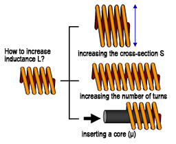
Based on this equation, the inductance can be increased by 1) increasing the sectional area S, 2) increasing the number of turns N, or 3) increasing the permeability µ by inserting a core.
Inductor-related Graphical Symbols for Electricity
| Symbols | |
|---|---|
| Inductor (air core) |  |
| Inductor (iron core) |  |
| Transformers |  |
Voltage and Current of Inductors
As explained in connection with their structure, inductors are essentially wound wires and therefore, current basically flows through them when a voltage is applied. However, because inductors are components designed to use the action of electromagnetic induction, current does not simply flow. The action of inductors when DC or AC is applied will be described here.
●When DC is applied
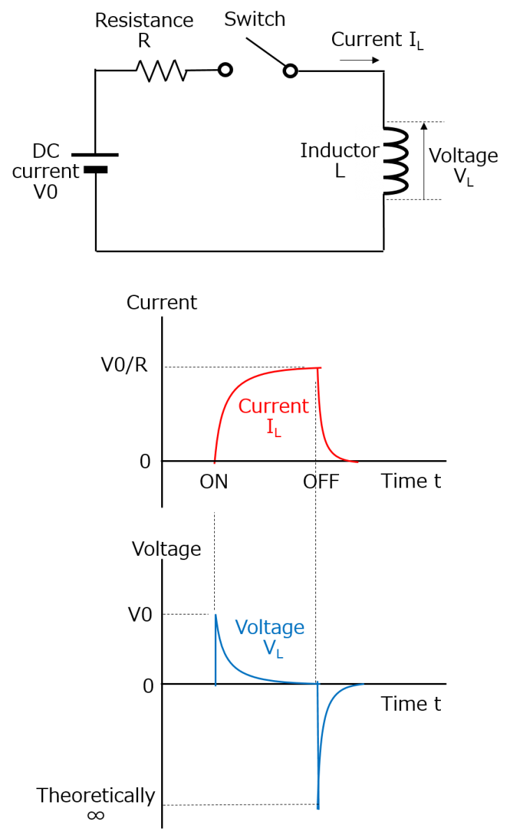
As shown by the circuit diagram, when the switch is turned on to apply DC to the inductor, current flows through the inductor, changing a magnetic flux that is generated by changes in the current flowing through the inductor (wound wire), thereby generating an electromotive force (induction electromotive force) on the inductor. Since the inductor is basically a single wound wire, this is referred to as "self-induction." This electromotive force is generated in a direction opposite to that of the current and restricts any increase in current. Conversely, the electromotive force restricts any decrease in current when the switch is turned off.
Although the current (IL)starts flowing when the switch is turned on, its increase is restricted by the electromotive force. Therefore, the current rises with a given time constant, and after the rise, a constant current flows depending on the resistance component. When the switch is turned off, the current falls; however, it becomes zero with a given time constant.
The voltage (VL) indicates the electromotive force of the inductor when the switch is turned on and off. As shown by the equation, the electromotive force generated on the inductor is proportional to the change rate of the current (ΔI /Δt).
ΔI
Δt
- V
- : Electromotive force(V)
- L
- : Inductance(H)
- ΔI /Δt
- : Change rate of the current(A/s)
As shown by the current waveform diagram, because the current increases relatively slowly when the switch is turned on, the electromotive force rises only up to the power supply voltage. When the switch is turned off, because the current is cut off instantaneously, the decrease in current is sudden compared to when the switch is turned on. As a result, the change rate as a function of time is higher, generating a higher electromotive force.
It should be noted that the reason the current does not become zero instantaneously when the switch is turned off is the discharge current flowing between the switch terminals due to the high voltage generated at the inductor.
能Inductors can generate such a high electromotive force because, as described in the section "What Are Inductors?" at the beginning, an inductor can "convert electric energy to magnetic energy and store it inside the inductor." The storable energy can be expressed by the equation below and is proportional to the magnitude of the inductance.
1
2
- W
- : Energy(J)
- L
- : Inductance(H)
- I
- : Current(A)
●When AC is applied
- First, the voltage becomes high when the current rises from zero because the change rate of the current is highest. However, the voltage decreases with a decrease in the rising speed of the current and becomes zero when the current reaches its maximum value (the change rate of the current is zero).
- The generation of a negative voltage starts when the current starts falling from its maximum value; the voltage reaches its minimum value when the current becomes zero (maximum change rate of the current).
- Regions (3) and (4) can be understood in the same manner as above.
Looking at these current and voltage waveforms, you will see that when the current waveform is sinusoidal, the voltage waveform is also sinusoidal, and the current waveform is behind the voltage waveform by 1/4 cycle (the phase of the current is behind by 90°).
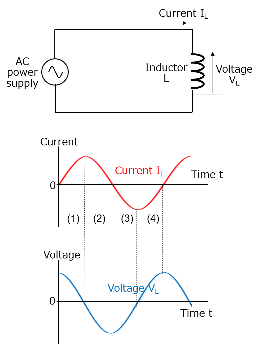
In addition, a larger voltage is generated when the current change is larger, which means that a larger voltage is generated at higher frequencies at which current changes are larger.
However, because the voltage of actual inductors is the same as the voltage of AC power supplies, increasing the frequency at a constant voltage will decrease the flowing current when considering the voltage as the reference.
In other words, in the case of AC, inductors work like resistors, passing the flowing current less easily at higher frequencies.
This is referred to as the inductive reactance (XL) of coils. The inductive reactance and the flowing current can be expressed by the equation below.
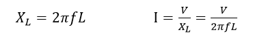
- XL
- Inductive reactance (Ω)
- f
- frequency(Hz)
- L
- Inductance(H)
- V
- AC voltage(V)
- I
- AC current(A)
Comparing Inductors and Capacitors
The table below summarizes the features of inductors in comparison with capacitors based on the explanation above.
As shown by the table, inductors and capacitors are electronic components with precisely opposite characteristics.
| Items | Inductors | Capacitors |
|---|---|---|
| Voltage-current relationship | A larger voltage is generated when the change rate of the current is higher. | A larger current flows when the change rate of the voltage is higher. |
| DC current | Pass | Do not pass |
| AC current | Pass less easily at higher frequencies | Pass more easily at higher frequencies |
| Phase of current with respect to voltage | Behind by 90° | Ahead by 90° |
Related product information
Tags related to this article

This document summarizes the Basic Knowledge of Inductors posted as technical information for the Optimal Solutions for Circuit Design.

