Basic Knowledge of LC Filters
2018-07-23
LC filters refer to circuits consisting of a combination of inductors (L) and capacitors (C) to cut or pass specific frequency bands of an electric signal.
Capacitors block DC currents but pass AC more easily at higher frequencies. Conversely, inductors pass DC currents as they are, but pass AC less easily at higher frequencies.
In other words, capacitors and inductors are passive components with completely opposite properties. By combining these components with opposite properties, noise can be cut and specific signals can be identified.
1. Types of LC Filters
LC filters are broadly classified into three types.
-
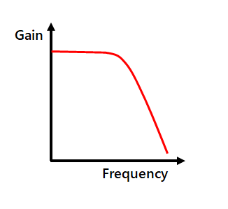
Low-pass Filters (LPF)
Low-pass filters are filter circuits that pass DC and low-frequency signals and cut high-frequency signals.
They are the most widely used filter circuits and are mainly used to cut high-frequency noise.
In audio, they are also used to cut treble/mid-range sound components of bass speakers.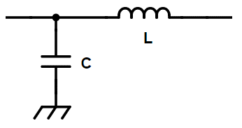
-
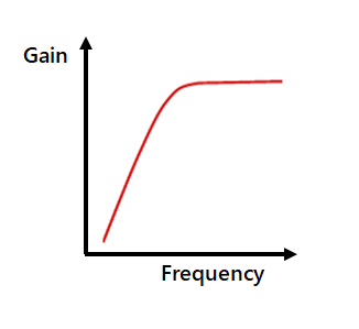
High-pass Filters (HPF)
High-pass filters are filter circuits that cut DC and low-frequency signals and pass high-frequency signals.
They are used to cut low-frequency noise in the audible range, cut mid-range/bass sound components of treble speakers, etc.
-
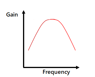
Band-pass Filters (BPF)
Band-pass filters are filter circuits that pass only signals at a specific frequency and cut signals at other frequencies.
They are used for radio tuning (frequency adjustment) or for cutting the bass/treble sound components of mid-range speakers, etc.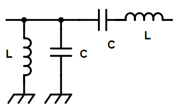
2. Types of Low-pass Filters
Although capacitors and inductors each have noise removal capabilities on their own, combining these two components will achieve a significant level of noise removal. Inductors connected in series block high-frequency noises, whereas capacitors connected in parallel work to bypass high-frequency noises.
However, noise removal effects change depending on the magnitude of the external impedance on the input and output sides. For example, even if a low-impedance capacitor is used to bypass noise, the noise will flow to the load side if the output impedance is lower. Conversely, even if a high-impedance capacitor is used to block noise, the noise will flow to the load side if the output impedance is higher. Therefore, when the external impedance is high, capacitors should be placed nearby, and when it's low, inductors should be used.
The four types of low-pass filters shown below are used by taking external impedances into consideration
-
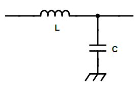
L-type Filter

When the input impedance ⇒ High
and the output impedance ⇒ Low -
L-type Filter
When the input impedance ⇒ Low
and the output impedance ⇒ High -
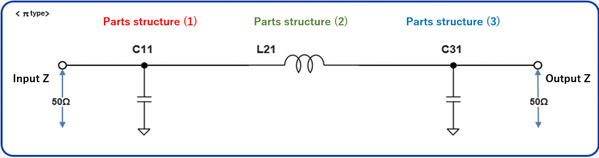
π-type Filter
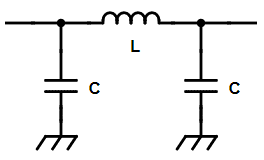
When the input impedance ⇒ High
and the output impedance ⇒ High -
T-type Filter

When the input impedance ⇒ Low
and the output impedance ⇒ Low
It should be noted that π- and T-type filters have better noise removal effects than the L-type, which should be taken into consideration when selecting circuits.
3. Component Selection for Low-pass Filters
To remove noise from a signal waveform in a signal circuit, it is necessary to select the constants of components that enable significant attenuation at the noise frequency rather than at the signal frequency. To remove noise from a DC voltage in a power supply circuit, it is necessary to consider only the attenuation amount at the noise frequency because the DC attenuation is zero.
The attenuation characteristics (change in attenuation amount depending on the frequency) of a filter can be calculated. However, because actual capacitors and inductors contain components that affect performance, in addition to pure capacitance and inductance, there is no simple method of calculating these characteristics.
The capacitor includes an equivalent series resistance (ESR) and an equivalent series inductance (ESL) in addition to a capacitance (C), whereas the inductor includes a DC resistance (DCR) and a parasitic capacitance (Cp) in addition to an inductance (L).

If a capacitor consists only of a C component, the impedance becomes lower and the noise absorption effect increases with higher frequencies.
However, the lower limit of the impedance is determined by the ESR in actual capacitors.
Furthermore, the impedance increases in high-frequency ranges due to the ESL, making it difficult to absorb noise.
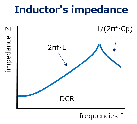
Likewise, if an inductance consists only of the L component, the impedance increases and the noise blocking effect becomes more significant at higher frequencies. However, in reality, the impedance decreases in high-frequency ranges due to Cp included in the inductor, thereby reducing the noise blocking effect.
Furthermore, because the value of each component changes depending on the frequency, it is quite difficult to select components by taking all these factors into consideration.

Therefore, simulation tools are often used to select LC filter components.
Simulation tools can usually calculate the accurate attenuation amount for each frequency using the S parameter and SPICE model provided by the component product number.
4. Example of Component Selection using a Simulation Tool
We will introduce an example of using the "Industrial & Automotive use LC filter simulator" available on the Panasonic website to select components for an LC filter intended to prevent the leakage of radio noise from an automotive ECU.
There is radio noise in the AM band (around 1 MHz) and FM band (around 80 MHz). Components that satisfy the attenuation amount criteria of -60 dB or more in these two frequency bands will be selected.
Please note that the prerequisite input/output impedance is 50 Ω.
- Target frequencies: 1 MHz, 80 MHz
- Target attenuation amount: -60 dB
- Input/output impedance: 50 Ω
1) Select the circuit
Select an L-type, π type, or T-type circuit
In this example, the π type is selected, and the input/output impedance is specified as 50 Ω.
2) Select the component
Select a capacitor part number and an inductor part number out of the registered candidate part numbers.
In this example, simulations were conducted with the following two conditions: (1) 100 μF capacitors and a 10 μH inductor; and (2) 10 μF capacitors and a 1 μH inductor.
| Parts structure (1) | |
|---|---|
| Circuit number | Part number |
| C11 | EEHZA1H101P |
| Parts structure (2) | |
|---|---|
| Circuit number | Part number |
| L21 | ETQP5M100YFM |
| Parts structure (3) | |
|---|---|
| Circuit number | Part number |
| C31 | EEHZA1H101P |
| Parts structure (1) | |
|---|---|
| Circuit number | Part number |
| C11 | EEHZA1J100P |
| Parts structure (2) | |
|---|---|
| Circuit number | Part number |
| L21 | ETQP3M1R0KVP |
| Parts structure (3) | |
|---|---|
| Circuit number | Part number |
| C31 | EEHZA1J100P |
3) See the simulation results
The simulation results indicated that the combination of the Selection (2) met the target values. In actual use, a variety of circuit and component combinations are simulated to select the optimal components.

In this simulation, the combination of small C and L values, rather than that of large C and L values, satisfied the target value. This is because the capacitors' ESL and inductors' Cp had a significant impact in high-frequency ranges.
In low-frequency ranges (approx. 0.1 MHz or lower), because the ESL and Cp have little impact, the attenuation amount is determined almost only by the C and L values. Therefore, the attenuation amount of the Selection (1) with large C and L values was large. However, in high-frequency ranges such as an FM band (80 MHz), the attenuation amount of the Selection (1) with large ESL and Cp was small, thereby causing a reversal in attenuation amount.
(In components with identical specifications, if the C value is large, so is the ESL, and if the L value is large, so is Cp.)
As described above, when designing LC filters, capacitors' ESL and inductors' Cp need to be taken into consideration for component selection in order to avoid unexpected results.
5. Related product information
6. LC filter simulator
The Industrial & Automotive use LC filter simulator enables the simulation of attenuation amounts when configuring a filter using Panasonic's power inductor and aluminum electrolytic capacitor suitable for industrial & automotive use.
7. Tags related to this article

This document summarizes the LC filter-related articles posted as technical information for the Optimal Solutions for Circuit Design.


