What is a Telematics Control Unit (TCU)?
- Equipment configuration and key points for achieving higher performance -
2022-12-21
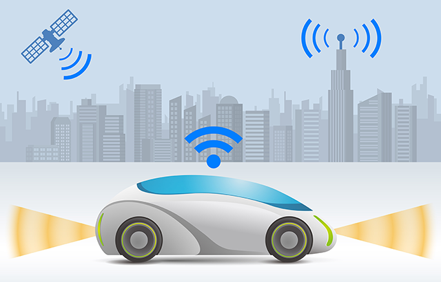
A TCU refers to a communication unit for two-way information communication between a vehicle and external network. With the spread of autonomous driving vehicles and connected cars in the future, the number of TCUs installed in vehicles is expected to increase. This article explains the functions and system configuration of TCUs, and also introduces the lineup of electronic components that make up TCUs.
1. What is a TCU?
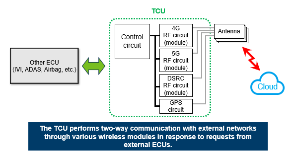
A TCU (Telematics Control Unit) refers to a communication unit for two-way information communication between a vehicle and the outside world in response to requests from ECUs (Figure 1). A TCU is connected to an external network environment through wireless modules. Through various types of communication, a TCU is responsible for improving vehicle functions and comfort (navigation assistance, etc.) and providing driving assistance (safe driving).
By installing a TCU, a vehicle emergency call system (eCall) and OTA (Over the Air) can be achieved. eCall is a system that transmits vehicle status and location information to an emergency center in the event of an accident. On the other hand, OTA refers to technology for transmitting and receiving data through wireless communication.
2. TCU market trend
The number of TCUs installed is said to be about half of the total number of vehicles. In the future, it is expected that the number of TCUs installed will increase along with the progress of autonomous driving and the spread of connected cars. Since high information processing performance is required, TCUs will have to support various communication methods such as 5G and DSRC in the future.
High-speed communication is essential for transmitting and receiving large amounts of data between TCUs and other devices. The power consumption of TCUs tends to increase as the amount of information processed increases. In other words, electronic components that make up TCUs will require "higher current," "lower loss," "high frequency operation," and "miniaturization."
3. TCU system configuration
3-1. Overview
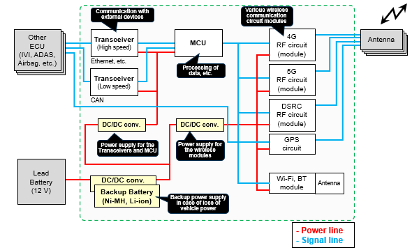
The TCU and its peripheral devices are connected as shown in Figure 2 below. The inside of the TCU is made up of transceiver circuits that communicate with various automotive ECUs, wireless modules that communicate with external devices, a microcomputer that processes bidirectional data, and DC/DC converter power supply circuits required to operate these other constituent circuits. In addition, the vehicle is equipped with a lead-acid battery (voltage of 12 V), which supplies power to various devices including the TCU. When the lead-acid battery fails in an accident, etc., will the entire system go down? In fact, the TCU is equipped with a backup power supply so that the system can continue to operate for a certain period of time even if the lead-acid battery cannot supply power. "eCall" uses this mechanism, and even if most of the vehicle's systems go down due to an accident, only the TCU uses the backup power supply to transmit an emergency warning to the emergency center.
3-2. DC/DC converter
A DC/DC converter refers to a circuit that converts a DC voltage into a different DC voltage. For example, it is responsible for converting a high voltage, such as battery voltage, to the voltage value required by each circuit such as microcomputers and communication modules. As shown in Figure 3, a DC/DC converter is mainly composed of FETs, coils, and capacitors. In general, DC/DC converter circuits use conductive polymer hybrid aluminum electrolytic capacitors for noise reduction at the input and smoothing at the output, automotive power inductors for voltage conversion, and chip resistors (high-precision chip resistors) for voltage measurements.
Noise reduction, switching, and smoothing ―― Conductive polymer hybrid aluminum electrolytic capacitor
POINT- ❶ Its high capacitance, low ESR, and high ripple performance contribute to circuit miniaturization and higher power features (low voltage and high current).
- ❷ Improved capacitance characteristics at high frequencies contribute to the elimination of noise, including high frequency components generated by high frequency switching of circuits over a wide band of frequencies.
Voltage conversion ―― Automotive power inductor
POINT- ❶ Contributes to circuit miniaturization and higher power features (low voltage and high current) due to the low loss and high current performance of metallic magnetic materials.
- ❷ Improved loss characteristics (low ACR) at higher frequencies contribute to the suppression of losses in high frequency switching circuits.
Voltage measurement ―― Chip resistor (high-precision chip resistor)
POINT- ❶ Contributes to the high-precision control of circuit output characteristics through the low resistance tolerance and low TCR performance with a thin-film structure.

3-3. Transceiver I/F
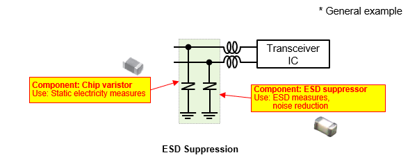
As shown in Figure 4, a transceiver circuit uses two lines to communicate with external devices (CAN, Ethernet, etc.). Care must be taken for static electricity and noise for the circuit. This is because when static electricity or noise enters from the communication line, this can lead to the failure of electronic components in the worst case. It is common to configure a transceiver circuit by using a chip varistor for static electricity measures and an ESD suppressor for ESD noise reduction.
ESD measures, noise reduction: ―― Chip varistor, ESD suppressor
POINT- ❶ Contributes to the suppression of electrostatic (ESD) noise while maintaining circuit communication quality with a lineup of products having a wide range of capacitance characteristics.
- ❷ Chip varistors support low to high communication speeds with capacitance characteristics ranging from 8 to 250 pF.
- ❸ ESD suppressors support high-speed communication speeds with their capacitance characteristics of 0.1 pF.
4. Summary
With the spread of autonomous driving vehicles and connected cars, the number of TCUs installed in vehicles is expected to increase. Such vehicles will need to support various communication methods such as 5G and DSRC to handle large amounts of data communication. In order to allow TCUs to handle large amounts of data, their constituent electronic components must have "high current," "low loss," "high frequency operation," and "small sizes." Aiming for TCU applications, Panasonic Industry offers a wide product lineup of highly functional devices that meet various requirements (Table 1).
| Components | Features | Large current | Low loss | High frequency | Miniaturization |
|---|---|---|---|---|---|
Conductive polymer hybrid aluminum electrolytic capacitor |
Low ESR High-reliability |
✔ | ✔ | ✔ | ✔ |
Automotive power inductor |
High current, low loss High-reliability |
✔ | ✔ | ✔ | ✔ |
Chip resistor (high-precision chip resistor) |
High-precision, high heat resistance | ✔ | |||
Chip varistor |
Miniaturization and weight reduction | ✔ | |||
ESD suppressor |
Low capacitance Ultra high-speed data I/F | ✔ | ✔ |

