Basic Knowledge of Power Circuits (3)
-Switching regulator design procedure-
2019-09-24
In this article, we are going to discuss an example of a switching regulator design flow.
Selecting a switching power supply (switching regulator) IC
A switching power supply, which is widely applied to digital equipment and household appliances, etc., can be constructed by combining discrete components (separate components) including operational amplifiers. However, constructing a switching power supply from scratch takes many man-hours for operation analyses and verifications, and it requires a number of those discrete components as well. It also gives you the additional trouble of requiring the switching power supply to be equipped with various protection functions, such as a function to limit current flows in the event of a short circuit. For these reasons, people usually decide to use a commercially sold switching power supply IC, which has integrated functions and is guaranteed to operate properly (see Table 1).
To select an optimum switching power supply IC, you have to take account of basic specifications, such as the voltage supplied to a system (input voltage) and the voltage/current applied to a load circuit (output voltage/output current), as well as other requirements, such as estimated fluctuations in the input voltage and consumption current flow in the load circuit, allowable output voltage error, and environmental temperature range. Based on these specifications and requirements, check the lineup of components found on a vendor's website and then choose the switching power supply IC you need using a selection function embedded in the page. Obviously, circuit size, cost, heat conversion efficiency, and the vendor's sales performance are also important factors you should take into consideration.
| Item | Switching controller IC | Switching regulator IC | Switching power supply module |
|---|---|---|---|
| Configuration | Only the control circuits, such as feedback circuits and oscillation circuits for generating a switching frequency, are integrated into this circuit. | In addition to control circuits, such as a feedback circuit, MOSFET drivers and small MOSFETs are integrated into this circuit. | Almost all kinds of components needed to make up a switching power supply are packaged and sealed in a single module. |
| Degree of integration | Low ←-------→ High | ||
| Major external components | Input/output capacitors, output inductor, resistor, MOSFET (MOSFET driver) | Input/output capacitors, output inductor, resistor | Some capacitors and resistors |
| Features | This IC allows a selection of a MOSFET to be incorporated, and it is therefore recommended to be used for power circuits with a relatively large output current. | This IC allows a selection of a MOSFET to be incorporated, and it is therefore recommended to be used for power circuits with a relatively large output current. | This module hardly requires design work. A high-power output version of the 100 A class is now available. Its component cost, however, is slightly high. |
Selecting an output capacitor and an output inductor
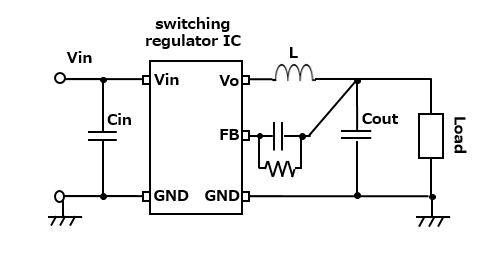
After selecting the switching power supply IC, you will proceed with the selection of passive components, such as a resistor, capacitor, and inductor while referring to recommended component constants listed in application notes, etc., for the switching power supply IC. Among these components, an output capacitor (denoted as Cout in Fig. 1) and an output inductor (denoted as L in Fig. 1) are most important.
Selecting an output capacitor
When selecting an output capacitor, you should pay attention to two factors: capacitance characteristics and equivalent series resistance (ESR).
For example, a multilayer ceramic capacitor (MLCC) often used in a switching power supply is well known for its disadvantageous capacitance characteristics: the capacitance drops depending on the temperature or a DC bias (see Fig. 2).
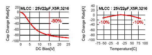
Temperature characteristics of MLCC series products are indicated by EIA standard codes. An MLCC with a temperature characteristics code (EIA standard code) "X5R" shows a little drop in the capacitance in high temperatures. An MLCC with a temperature characteristics code "Y5V," however, loses its capacitance significantly in high temperature, so you have to be careful about using this type of MLCC. You need to examine how higher an ambient temperature goes during the operation of an output capacitor and select a capacitor adequate for a given temperature condition.
An MLCC with a high dielectric constant has a tendency for its capacitance to drop significantly when a direct voltage is applied to the MLCC. Selecting a capacitance value for the MLCC by checking its nominal capacitance only, therefore, could lead to a case where the MLCC does not show the capacitance characteristics you expect to observe under actual service conditions.
To deal with these problems, see technical information in "Conductive Polymer Capacitor Provides Solution to Problems with MLCC."
An ideal capacitor would have the capacitance (C) element only, but a real capacitor is never like that. A capacitor you actually use includes, in addition to the capacitance (C) element, an equivalent series resistance (ESR) element, an equivalent series inductance (ESL) element, and an insulation resistance (IR) element (see Fig. 3).
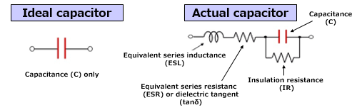
Among circuit elements shown in Fig. 3, the ESR, which is a resistance element, could become the cause of a voltage drop. In response to changes in load current, the voltage drop changes, resulting in a drop in voltage applied to the load. When the ESR has a high resistance value, it leads to a reduction in the effect of absorbing a ripple current caused by switching, or to heat generation by the ripple current flowing through the ESR, which shortens the service life of the capacitor. An ESR with a high resistance value is therefore used under limited service conditions, which should be noted well.
In general, a tantalum capacitor and an aluminum electrolytic capacitor each have an ESR with a high resistance value. An MLCC and a conductive polymer capacitor each, on the other hand, have an ESR with a low resistance value.
To know more about the ESR of the capacitor, see technical information in "Basic Knowledge of Capacitors (1) – Structure, Usage, and Characteristics" and "Case of Replacing Input/Output MLCC with Hybrid Capacitor in Switching Power Supply."
- Capacitance characteristics
- Equivalent series resistance (ESR)
Selecting an output inductor
When selecting an output inductor, you should pay attention to the nominal inductances specified by the vendor. A nominal inductance is an inductance value that is measured at a certain frequency and usually includes a margin of error of ±30%. When using an inductor as an output inductor in a switching power supply, you need to confirm that the inductor offers an intended inductance at the switching frequency by checking the characteristic graph on a data sheet.
Applying a DC bias to the inductor reduces its inductance. A current that causes the inductance to drop by 30% from its initial value is indicated by a spec item in "Rated current: DC superposition" (see Table 2). To know more about these inductor characteristics, see technical information in "Basic Knowledge (2) of Inductors (Coils) –Characteristics and Types." Perhaps the inductor's characteristics are more difficult to understand intuitively than the capacitor's or resistance's. We recommend you to check technical information provided by vendors or make inquiries to vendors and select an inductor appropriate for the power supply you intend to design.
| Spec item | Meaning/definition |
|---|---|
| Inductance (L value) [µH] | The L value is determined based on a measured frequency (100 kHz). |
| DC resistance (DCR) [Ω] | The resistance of a conductor (copper wire) making up the inductor |
| Rated current: temperature rise (⊿T) [A] | Current rating for a DC bias that, when applied to the inductor, causes the temperature of the inductor to rise by 40K |
| Rated current: DC superposition (⊿L) [A] | Current rating for a DC bias that, when applied to the inductor (superposed on an alternating current), causes the inductor's L value to drop 30% below its initial value |
Carrying out noise suppression measures in an upstream process in design work
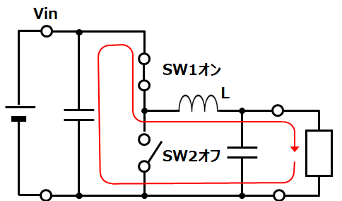
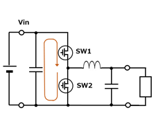
When you design a switching power supply circuit, you will face one major problem – noise. As described in "Basic Knowledge of Power Supply Circuits (2)," a switching element's frequent switching on and off at a switching frequency creates a loop that significantly changes current flow (Fig. 4), which consequently causes electromagnetic noise and ground noise (ground bounce), etc.


The noise created in a power circuit spreads, causing the whole circuit to behave unstably or even abnormally. This is a phenomenon called "autointoxication." In addition, such noise coming out of the power circuit affects other equipment, too. For example, noise generated by automotive equipment may mix into AM radio waves (526.5 kHz to 1606.5 kHz in Japan), making radio sounds noisy depending on frequencies included in the noise.
Because of these problems, taking noise suppression measures is essential for successful power circuit design, which must meet various electromagnetic interference (EMI) standard requirements specified for fields including household appliances and automobiles.
Taking noise suppression measures in an upstream process of the whole design work reduces costs and time. Specifically, devised board design and layout are important. This includes reducing the area of a current loop containing an input capacitor as much as possible; isolating the loop from an irrelevant incoming signal; making a circuit ground pattern as wide as possible (or adopting a multilayer board); and arranging filtering elements, such as a bypass capacitor, properly. Recently, a visualization method of current and impedance on the board using an electromagnetic analysis tool has been adopted.
A switching power supply IC that generates less noise due to its specially devised packaging is also available today. Choosing such a product may be a good solution to noise problems.
In this article, we have described general procedures for designing a switching power supply and typical points to note for design work. When carrying out actual design work, you need to take into consideration other conditions in addition to these procedures and points. We advise you to refer to power circuits with excellent product records, reference circuits provided by vendors, and other reference materials.
In the next article, we will discuss the power supply of an electronic control unit (ECU) that controls a car.
Related product information
Tags related to this article

This document summarizes the Basic knowledge of power supply circuit posted as technical information for the Optimal Solutions for Circuit Design.
