What Is an On-Board Charger (OBC) Incorporated in Electric Vehicles?
– AC/DC Conversion System That Allows Faster Battery Charging and is Highly Efficient –
2023-07-21
- What Is An On-Board Charger (OBC)?
- EV charging patterns
- Battery capacity and power output from the OBC
- Trends in the market and demand for the OBC
- The circuit configuration of the OBC
- Individual circuits and components
- Summary
- Related product information
- Related information
- Tags related to this article
An OBC is used when the battery of an electric vehicle (EV) is charged. It converts power from a charging station into the voltage the battery needs. EVs are expected to further increase in number, and an OBC with a higher power output is absolutely needed to charge batteries with larger capacities. This article will discuss the functions and system configuration of the OBC and will introduce the electronic components making up the OBC as well.
What Is An On-Board Charger (OBC)?
An OBC is a device that is used to charge a battery. It converts AC voltage from a charging station into the DC voltage the battery needs. The OBC is incorporated in electric vehicles (EV) and plug-in hybrid electric vehicles (PHEV). It charges these vehicles, using AC power from private residences' charging equipment or public charging stations. The power output from OBCs mainly ranges from 3.6 kW to 22 kW.
EV charging patterns
・Normal charging
In normal charging, the battery is charged to full. The battery of an EV is charged with AC voltage from a private residents' charging equipment or a public charging station. Generally, charging the battery fully takes about eight hours. In the case of normal charging, the OBC incorporated in the vehicle converts AC voltage into DC voltage applicable to the vehicle battery.
・Quick charging
Quick charging is charging to refill the battery in a short time. In quick charging, the charging station supplies DC voltage corresponding to the battery voltage, charging up the vehicle battery in a short time by quickly feeding the battery with large power. Quick charging, in general, takes about 30 minutes to 1 hour to finish, depending on the battery capacity. You will find those chargers for EVs in a lot of expressway rest areas, commercial establishments, etc.
| Charging pattern | Charging station | Location | OBC | Charging time | Application |
|---|---|---|---|---|---|
| Normal charging | Supply AC voltage (200 V, 400 V, etc.) |
Private houses, company buildings, etc. | OBC converts AC voltage into DC voltage (battery voltage) | Long (about eight hours) | Charging the battery full |
| Quick charging | Supply DC voltage directly to the battery | Expressways, commercial establishments, etc. | OBC is not used | Short (0.5 hour to 1 hour) |
Refilling the battery quickly |
Battery capacity and power output from the OBC
Battery capacities vary depending on car types (compact car, SUV, sports car, etc.). Power output from the OBC varies depending on countries and regions but is generally specified as power output in which the battery is fully charged in eight hours or so.
Trends in the market and demand for the OBC
EVs are expected to further increase in number. As battery capacities get larger, OBCs with a higher power output will become an absolute necessity. In addition to that, we have to meet demand for a shorter charging time and smaller batteries as well. To meet these challenges, it is important to provide electronic components with these properties: "high voltage (high withstand voltage)," "large current," "low loss," "high resistance to heat," and "small size."
The circuit configuration of the OBC
Overall configuration
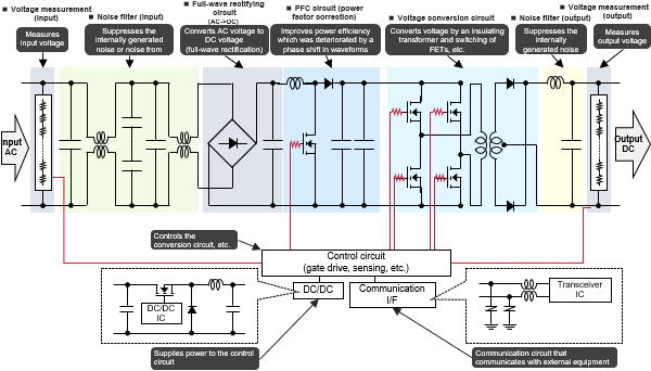
An OBC system is composed of the following components.
- Voltage measuring circuit (input): This circuit measures voltage for controlling a conversion circuit.
- Noise filter (input): This filter suppresses internal noise or noise from external equipment.
- Full-wave rectifying circuit: This circuit rectifies AC voltage into DC voltage.
- Power factor correction (PFC) circuit: This circuit improves power efficiency deteriorated by a phase shift in the waveform.
- Voltage conversion circuit: This circuit converts voltage by an insulating transformer and switching of FETs, etc.
- Noise filter (output): This filter suppresses internally generated noise.
- Voltage measuring circuit (output): This circuit measures voltage for controlling the conversion circuit.
- Control circuit: This circuit controls the conversion circuit, etc.
- DC/DC converter: The converter supplies power to the control circuit.
- Communication I/F: This is a communication circuit that communicates with external equipment.

Individual circuits and components
Voltage measuring circuits (input/output)
The voltage measuring circuits measure an input voltage and an output voltage for carrying out control of the voltage conversion circuit. At each voltage measuring circuit, in general, the voltage across both ends of resistances connected in series is measured.
Voltage measurement ―― Chip resistor (high-precision chip resistor)
POINT- ❶ A chip resistor with a thin-film structure offers a small resistance tolerance and a low TCR, contributing to high-precision control of the output characteristics of the circuit.
Noise filter (input/output)
Each noise filter suppresses internally generated noise or noise from external equipment to prevent malfunctioning of the system.
In general, the filter has a large inductor and film capacitors combined together.
Noise elimination ―― Film Capacitors (Automotive, Industrial and Infrastructure Use)
POINT- ❶ High reliability: The film capacitor offers high resistance to humidity and thermal impact, and conforms to AEC-Q200.
- ❷ High safety: With its security mechanism (fuse), the film capacitor ensures high safety (it puts the circuit into an opened state in failure mode).
Full-wave rectifying circuit, PFC circuit
The full-wave rectifying circuit rectifies AC voltage into DC voltage, and the PFC circuit improves power efficiency deteriorated by a phase shift during the rectifying process. In the rectifying process, in general, capacitors are used to smooth AC voltage to be converted into DC voltage.
The PFC circuit remedies a phase shift by switching actions, and therefore usually includes a coil and capacitors.
Voltage smoothing ―― Film Capacitors (Automotive, Industrial and Infrastructure Use)
POINT- ❶ High reliability: The film capacitor offers high resistance to humidity and thermal impact, and conforms to AEC-Q200.
- ❷ High safety: With its security mechanism (fuse), the film capacitor ensures high safety (it puts the circuit into an opened state in failure mode).
Voltage conversion circuit
The voltage conversion circuit converts voltage through switching and transformation by switching elements and a transformer.
The switching elements switch on and off to smooth AC voltage, but these switching actions create noise. For this reason, gate terminals of these switching elements are usually made of resistances.
Suppressing gate-driving noise by the switching element ―― Chip resistor (small and high-power chip resistor)
POINT- ❶ With its original resistance pattern, electrode structure, etc., the chip resistor is small in size and yet handles high-power operations, thus contributing to a reduction in the size of the circuit.
DC/DC converter
In a DC/DC converter circuit, in general, a conductive polymer hybrid aluminum electrolytic capacitor is used to eliminate noise to the input end and to smooth voltage output from the output end, and an Automotive power inductor is used for voltage conversion.
Noise elimination, switching, and smoothing ―― Conductive polymer hybrid aluminum electrolytic capacitor
POINT- ❶ A capacitor offers high capacitance, low ESR, and high ripple-suppression performance, contributing to a reduction in the size of the circuit and an increase in the power capacity (low voltage and large current) of the circuit.
- ❷ Having capacitance characteristics to cut off high-frequency components, the capacitor eliminates a wide range of high-frequency noise that is generated by the high-frequency switching of the circuit.
Voltage conversion ―― Automotive power inductor
POINT- ❶ An inductor made of a metal magnetic material suffers less power loss and carries a large current, contributing to a reduction in the size of the circuit and an increase in the power capacity (low voltage and large current) of the circuit.
- ❷ Having loss characteristics in a higher frequency range (low ACR), the inductor contributes to the suppression of power loss caused by high-frequency switching of the circuit.
Communication I/F
A communication I/F circuit communicates with external equipment (CAN, Ethernet, etc.) through two communication lines. If noise or static electricity enters these communication lines, it may cause a transceiver IC to fail.
To prevent such a problem, a transceiver circuit is usually provided with chip varistors serving as electrostatic control measures.
ESD noise elimination ―― Chip varistor
POINT- ❶ With a wide range of capacitance characteristics, these components suppress electrostatic noise (ESD) while keeping the communication quality of the circuit intact.
- ❷ With its capacitance ranging from 8 pF to 250 pF, the chip varistor operates effectively at low and high communication speeds.
Summary
An OBC is an important device that is used when the battery of an EV or PHEV is charged. Therefore, as EVs increase, vehicles equipped with OBCs will increase. In addition, to charge batteries with larger battery capacities, we need to provide OBCs with a higher power output. There will be increasing demand that in-vehicle electronic components have these properties: "high voltage (high withstand voltage)," "large current," "low loss," "high resistance to heat," and "small size." Panasonic Industry offers a wide variety of products for use in OBC (Table 2).
| Component | Feature | High voltage | Large current | Low loss | Small size | High resistance to heat | High precision |
|---|---|---|---|---|---|---|---|
Conductive polymer hybrid aluminum electrolytic capacitor |
Low ESR High reliability |
✔ | ✔ | ✔ | ✔ | ✔ | |
Automotive power inductor  |
Large current, low loss High reliability |
✔ | ✔ | ✔ | ✔ | ||
 |
High precision, high resistance to heat | ✔ | ✔ | ✔ | ✔ | ✔ | |
Chip varistor |
Small and light | ✔ | |||||
Film Capacitors (Automotive, Industrial and Infrastructure Use) |
High reliability | ✔ | ✔ |


