- UA3P
- Outline
- Feature
- Specifications
- Examples
- Options
Software
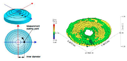
Circumferential scanning measurement software
The measured object is circumferentially scanned and measured.
· Hollow objects are also measureable.
· Up to 1200 concentric circles.
User-defined software (free-form curved surfaces, etc.)
Other formulae are supported in addition to the lens design formula that is registered as a standard feature.
The use of the C language for creating the design formula and the calculation part of a partial differential equation allows all of ISO10110-12 to be covered.
| ISO10110-12 | UA3P Design formula type | ||
|---|---|---|---|
| General secondary curve | Rotation symmetry | Ellipsoid | Rotation symmetry aspheric surface |
| Hyperboloid | |||
| Paraboloid | |||
| Spherical surface | |||
| Conical surface | User-defined formula | ||
| Flat face | Flat face | ||
| Rotational asymmetry | Ellipsoid Hyperboloid |
User-defined formula | |
| Paraboloid Conical surface |
|||
| Cylindrical face | Cylindrical | ||
| Toric | R center is constant | ||
| X: Non-circular arc, Y: Circular arc | |||
| Undefined | Doughnut | ||
| User-defined formula | |||
* Limited to the case that can be expressed by applicable Z = f (x, y).
Software for creating point group data design formula
A rectangular curved surface is created using the spline function with respect to given 3D point group data.

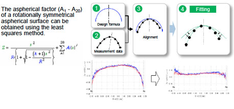
Fitting software (rotation symmetry)
A previously unknown design formula of a measured object can be obtained from the measurement data.
Auto-measurement
Applicable model: All models except for UA3P-400T
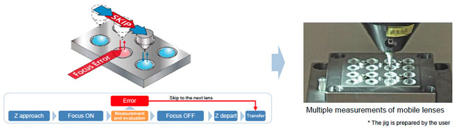
Fully automated, including probe movement and focus ON/OFF
Supporting various errors
| Optional software | 500/550H | 650H/700H | 3000 | 300 | 400T | Notes | |
|---|---|---|---|---|---|---|---|
| 1 | Circumferential scanning measurement software | ||||||
| 2 | User-defined software | ||||||
| 3 | Base alignment software | ||||||
| 4 | Coordinate axis conversion software | ||||||
| 5 | Rotation symmetry fitting software | ||||||
| 6 | New diamond stylus correction software (on axis) | Supporting only data on axis | |||||
| 7 | Function for creating point group data design formula | ||||||
| 8 | Function for creating measurement data curve | ||||||
| 9 | Number of measuring points: 1 million, capture speed: 2000 points/sec |
||||||
| 10 | V-groove measuring software | ||||||
| 11 | Inclination and decentering evaluation software | ||||||
| 12 | High-inclination measuring software | ||||||
| 13 | Auto-measuring software | ||||||
| 14 | TopFlat centering software | ||||||
![]() :Available
:Available ![]() :Standard feature
:Standard feature ![]() :Not available
:Not available
Hardware
Stylus
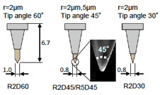
New diamond stylus for top-surface measurement
Supports precise shape measurement, such as of mobile lenses and diffracting gratings
Ruby stylus for top-surface measurement*1
Uses a high-sphericity ruby ball for general-purpose measurements
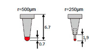
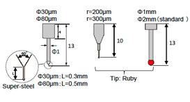
Stylus for side-surface measurement*2
Super-steel or ruby available for the tip.
Decenter and Tilt measurement jig
Decenter/Tilt measurement between lens faces
The lens is fixed on a jig provided with three reference balls for combination. Any decentering between the lens faces is evaluated by measuring both faces of the lens.

Aspherical face - Aspherical face lens
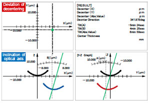
Example of evaluation of lens decenterand tilt
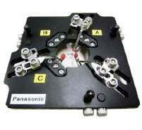
Decenter and tilt measurement jig
Observation camera
Applicable model: All models
A measuring point is magnified for display to enable easy positioning.
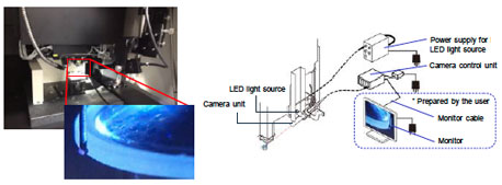
| CCD camera specifications | |
|---|---|
| Viewing field range | H8 mm x V6 mm |
| Effective pixels | 380,000 pixels (H768 x V494) |
| Observation magnification | 40x-50x (for a 17" monitor) |
| Video output terminal | BNC terminal |
| Lighting | LED coaxial epi-illumination |
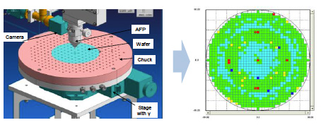
Wafer level lens (WLL)
Applicable model: UA3P-500H/650H/700H
| Optional hardware | 500/550H | 650H/700H | 3000 | 300 | 400T | Notes | |
|---|---|---|---|---|---|---|---|
| 1 | R2D45 Diamond stylus (new diamond stylus) | For measuring up to an inclination angles up to 60° | |||||
| 2 | R2D30 diamond stylus | For measuring inclination angles up to 70° | |||||
| 3 | R5D45 diamond stylus | The long-radius tip has high wear resistance. | |||||
| 4 | Ruby ball for calibrating diamond stylus | For calibrating tip R of diamond stylus | |||||
| 5 | R250 µm ruby stylus | ||||||
| 6 | Stylus for measuring R30 µm side surface | For measuring outlines of nozzles and detailed shapes | |||||
| 7 | Stylus for measuring R200 µm side surface | For measuring the outlines of lenses and molds | |||||
| 8 | Standard ball for calibrating small-diameter stylus | For calibrating tip R of stylus for side-surface measurement | |||||
| 9 | Inclination and decentering measuring jig ø3-26 mm |
Needs decenter and tilt evaluation software | |||||
| 10 | Inclination and decentering measuring jig ø20-55 mm |
Needs decenter and tilt evaluation software | |||||
| 11 | Inclination and decentering measuring jig ø50-100 mm |
Needs decenter and tilt evaluation software | |||||
| 12 | High-inclination measuring jig | ||||||
| 13 | Observation camera unit (Dedicated number for each model) |
||||||
| 14 | Wafer chuck and camera unit | For measuring wafer level lenses, evaluation software is needed | |||||
![]() :Available
:Available ![]() :Standard feature
:Standard feature ![]() :Not available
:Not available
* Precautions
*1 Note that the ruby stylus is at risk of breaking due to its large coefficient of friction while measuring aluminum lenses or surface-coated lenses.
*2 The stylus for side-surface measurement (ø30 µm - ø300 µm) may require an observation camera for measurement.
For other kinds of parts (stylus length, tip size or material), please ask at our sales office about the detail.