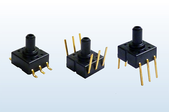
・Miniature size
・High precision pressure sensor (without amp.)
・Standard type(with glass base): Rated pressure 4.9kPa to 980.7kPa
・Economy type(without glass base): Rated pressure 40.0kPa
・High precision pressure sensor (without amp.)
・Standard type(with glass base): Rated pressure 4.9kPa to 980.7kPa
・Economy type(without glass base): Rated pressure 40.0kPa
Topics
- 2023-11-21 PS series is NOT Recommended for New Design.
- 2023-03-31 Some parts of PS Pressure Sensors has been discontinued.
- 2021-04-01 Some parts of PS Pressure Sensors are Not Recommended for New Design (12 part numbers).
- 2016-10-28 Registration certificates of quality and environment certifications (ISO, TS) are available for download
Basic Information
High precision pressure sensor (without amp.)


Features
-
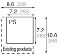
Ultra-miniature size: much more compact than the PF pressure sensors offered in the past
- Base area:7.2(W)×7.2(D) mm .283(W) × .283(D) inch
- Only 60% in mounting area and 91% in overall height of previous models (PF)
-
High-level precision and linearity
A high degree of precision and linear detector response have been achieved by applying the semiconductor strain gauge system. Highly reproducible based on repeated pressure.
-
Impressive line-up of models
- Taking their place alongside the standard 5kW bridge resistance models are those with a 3.3kW resistance which is optimally suited to 5V drive circuits.
-
Improved ease of DIP pin insertion into printed circuit boards
- The ends of the DIP pins are chamfered to ensure easy insertion into printed circuit boards.
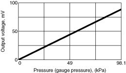
Example of pressure characteristics
(when the rated pressure is between
98.1 kPa{1.0kgf/cm2})Drive current: 1.5 mA rated current; ambient temperature: 25°C 77°F
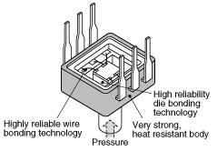
Cross-section of Sensor Chip

Appllications
- Industrial use: pressure switches and pneumatic components, compressed air pressure measuring devices and airbeds
- Medical use: blood pressure meters, oxygen generator and airbeds
- Others: pressure sensing devices for air pressure mediums
Rating/Performance
Standard (With glass base)
| Type of pressure | Gauge pressure | ||||
|---|---|---|---|---|---|
| Pressure medium | Air (For other medium, please consult us.) | ||||
| Rated pressure | Unit: kPa | 490.3 | 980.7 | 98.1 | 980.7 |
| Max. applied pressure | Twice the rated pressure | 1.5 times the rated pressure | Twice the rated pressure | 1.5 times the rated pressure | |
| Bridge resistance | 5,000±1000ohm | 3,300±700ohm | |||
| Ambient temperature | -20 to +100°C -4 to +212°F(no freezing or condensation) | ||||
| Storage temperature | -40 to +120°C -40 to +248°F(no freezing or condensation) | ||||
| Standard temperature | 25°C 77°F | 30°C 86°F | |||
| Temperature compensation range | 0 to 50°C 32 to 122°F | 0 to 60°C 32 to 140°F | |||
| Drive current (constant current) | 1.5 mA DC | 1.0 mA DC | |||
| Output span voltage | 100±40 mV | 65±25 mV | |||
| Offset voltage | ±20 mV | ||||
| Linearity | ±0.5%FS | ±0.6%FS | ±1.0%FS | ||
| Pressure hysteresis | ±0.4%FS | ±1.0%FS | |||
| Offset voltage-temperature characteristics (0 to 50°C 32 to 122°F) |
±5.0%FS | ±3.5%FS | |||
| Sensitivity-temperature characteristics (0 to 50°C 32 to 122°F |
±2.5%FS | ||||
- Unless otherwise specified, measurements were taken with a drive current of ±0.01 mA and humidity ranging from 25% to 85%.
- Please consult us if a pressure medium other than air is to be used.
- This is the regulation which applies within the compensation temperature range.
- Please consult us if the intended use involves a negative pressure.
Dimensions
Unit: mm inch
- Terminal direction: DIP terminal Direction opposite the pressure inlet direction ADP41**
- Terminal direction: DIP terminal Pressure inlet direction ADP42**
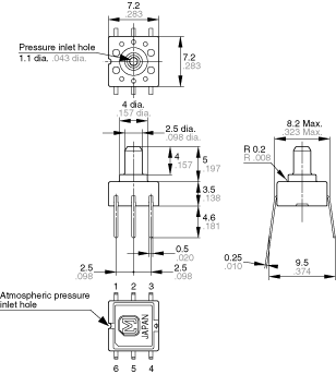
- Terminal direction: SMD terminal ADP4932, ADP4933
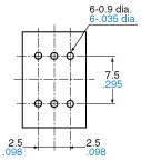
1.Terminal direction: DIP terminal Direction opposite the pressure inlet direction ADP41**
Dimensions
Tolerance: ±0.3 ±.012
Recommended PC board pattern
(BOTTOM VIEW)
Terminal connection diagram

| Terminal No. | Name |
|---|---|
| 1 | Power supply (+) |
| 2 | Output (+) |
| 3 | Power supply (-) |
| 4 | Power supply (-) |
| 5 | Output (-) |
| 6 | No connection |
*Leave terminal 6 unconnected.
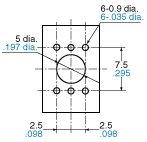
2.Terminal direction: DIP terminal Pressure inlet direction ADP42**
Dimensions
Tolerance: ±0.3

Recommended PC board pattern
(BOTTOM VIEW)
Terminal connection diagram

| Terminal No. | Name |
|---|---|
| 1 | Power supply (+) |
| 2 | Output (+) |
| 3 | Power supply (-) |
| 4 | Power supply (-) |
| 5 | Output (-) |
| 6 | No connection |
*Leave terminal 6 unconnected.
3.Terminal direction: SMD terminal ADP4932, ADP4933
Dimensions
Tolerance: ±0.3

Recommended PC board pattern
(BOTTOM VIEW)

Terminal connection diagram

| Terminal No. | Name |
|---|---|
| 1 | Power supply (+) |
| 2 | Output (+) |
| 3 | Power supply (-) |
| 4 | Power supply (-) |
| 5 | Output (-) |
| 6 | No connection |
*Leave terminal 6 unconnected.
