2023-05-31
Application
Technical information
What cameras are installed in ADAS and AD systems?
- Groups of devices that contribute to the enhanced performance of equipment -
Cameras used for automotive applications serve as equipment for sensing the surroundings of vehicles in ADAS (Advanced Driver Assistance Systems) and AD (Autonomous Driving) systems. There are three main types of cameras: sensing cameras, surround view cameras, and driver monitoring cameras. This article explains each camera module and introduces the lineup of electronic components that constitute the modules.
What cameras are used in ADAS and AD systems?
In ADAS and AD systems, camera, radar, LiDAR, sonar, and other technologies are combined to sense multiple directions both inside and outside the vehicle, thereby supporting safe driving. There are three main types of cameras installed in vehicles: sensing cameras, surround view cameras, and driver monitoring cameras. (Table 1)
| Equipment name | Mounting location & function |
|---|---|
| Sensing camera | Installed in the upper part of the windshield, it senses a wide area to ensure the safety of the front of the vehicle. |
| Surround view camera | Camera units are installed on the front, back, left, and right of the body of a vehicle to sense approximately 1 m around the entire perimeter of the vehicle and ensure safety in the vicinity of the vehicle. |
| Driver monitoring camera | Installed near the meter cluster of a vehicle, it senses the driver's health condition to ensure safe driving. |
Use of each camera
Table 2 below shows the functions and uses of sensing cameras, surround view cameras, and driver monitoring cameras. In particular, sensing cameras and driver monitoring cameras are involved in "control decisions" and "control instructions," and play a particularly important role in realizing AD (autonomous driving).
| Equipment name | Use | Sensing | Decide | Command | Application example |
|---|---|---|---|---|---|
| Sensing camera | AD (autonomous driving) ADAS (driving assistance) |
✔ | ✔ | ✔ | Various driving assistance systems LKA, LCA, AEB, etc. |
| Surround view camera | ADAS (driving assistance) Image display of the vehicle's entire surroundings |
✔ | ✔ | ✔ | Parking assist |
| Driver Monitoring camera | AD (autonomous driving) Monitoring of driver's awareness status |
✔ | ✔ | ✔ | DMS (driver monitoring system) |
Internal configuration of each camera
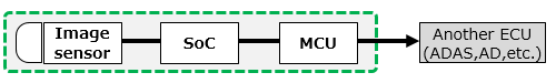
●Sensing camera, driver monitoring camera
An image sensor refers to a sensor that converts the light entering through the lens of a camera into electrical signals. The data sensed as signals are processed through an SoC (System on a chip). In addition, these cameras are equipped with a microcomputer to issue control commands to an external ECU.
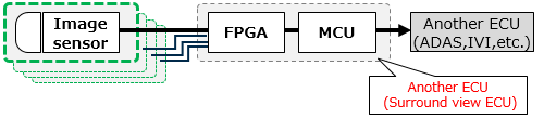
●Surround view camera
Unlike sensing cameras and driver monitoring cameras, this type of camera is equipped with multiple image sensors. This is because camera units are installed in multiple locations on the vehicle body to make up this type of camera. Acquired image data are integrated (synthesized) into one omnidirectional image by another ECU (surround view ECU, etc.).
| Equipment name | Circuit configuration |
|---|---|
| Sensing camera Driver monitoring camera |
 |
| Surround view camera |
 |
Camera market and equipment trends
Trends of the camera module market and equipment
With regard to market trends, the number of cameras installed in vehicles is expected to increase as the number of vehicles increases and the level of autonomous driving improves, and the performance of sensing functions is also expected to further improve. The functions and performance required for camera modules in the future include "higher power," "higher-speed communication," and "miniaturization and weight reduction." The requirements for each improvement are as follows.
●Higher power
The amount of data is expected to increase due to requirements for higher performance such as higher resolutions and higher dynamic ranges of image sensors. In addition, SoCs are also required to achieve faster and more precise recognition and decision processing. Higher power is essential as the power loss of electronic components increases due to the increased amount of data processing.
●Higher-speed communication
The increased amount of image data transmitted requires improved high-frequency processing and high-speed data transmission.
●Miniaturization and weight reduction
In addition to the above challenges, it is necessary to reduce the size of electronic components.
Circuit configuration of each camera module
This section explains the circuit configuration of sensing cameras, driver monitoring cameras, and surround view cameras.
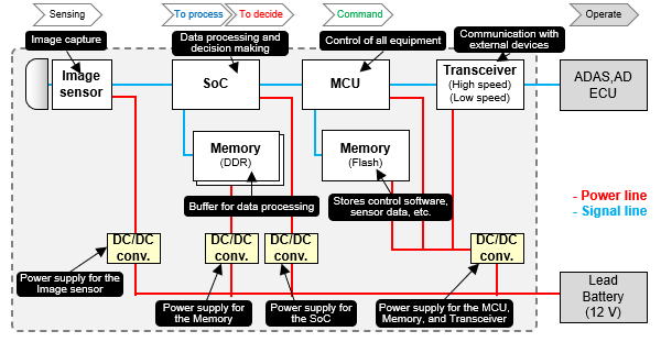
Sensing camera, driver monitoring camera
Sensing cameras and driver monitoring cameras are made up of the following components, with their circuit configuration shown in Figure 1.
●Image sensor: Sensor necessary for capturing images. It converts the light coming through the camera lens into electrical signals.
●SoC: Device for processing data acquired by an image sensor.
●MCU (microcomputer): Feeds control instructions such as "apply the brake" and "turn the steering wheel" to an external ECU.
●Transceiver: Device for communicating with an external device.
●Memory (DDR): Used as a buffer during data processing.
●Memory (flash): Stores control software and sensor data.
●DC/DC converter: Converts the voltage from a lead battery to the voltage required by each electronic component.
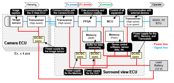
Surround view camera
A camera ECU and surround view ECU are used to make up a surround view camera. Unlike other types of camera modules, multiple camera units are mounted on a vehicle to make up the surround view camera. Therefore, transceiver circuits must communicate larger amounts of data. An FPGA is used to integrate the acquired image data into one, where image processing is performed at high speed.
Other configurations are the same as those of sensing cameras and driver monitoring cameras.
Specific examples and uses of each component
DC/DC converters and transceiver circuits are commonly used in sensing cameras, driver monitoring cameras, and surround view cameras. This section explains the electronic components that constitute each circuit and their effects.
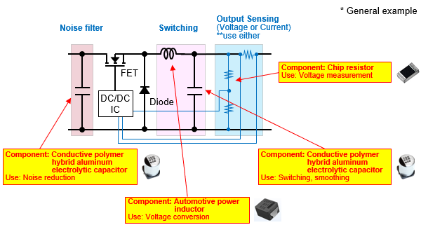
DC/DC converter
n general, DC/DC converter circuits use conductive polymer hybrid aluminum electrolytic capacitors for noise reduction at the input and smoothing at the output, automotive power inductors for voltage conversion, and chip resistors (high-precision chip resistors) for voltage measurements.
Noise reduction, switching, and smoothing ―― Conductive polymer hybrid aluminum electrolytic capacitor
POINT- ❶ Its high capacitance, low ESR, and high ripple performance contribute to circuit miniaturization and higher power features (low voltage and high current).
- ❷ Improved capacitance characteristics at high frequencies contribute to the elimination of noise, including high frequency components generated by high frequency switching of circuits over a wide band of frequencies.
Voltage conversion ―― Automotive power inductor
POINT- ❶ Contributes to circuit miniaturization and higher power features (low voltage and high current) due to the low loss and high current performance of metallic magnetic materials.
- ❷ Improved loss characteristics (low ACR) at higher frequencies contribute to the suppression of losses in high frequency switching circuits.
Voltage measurement ―― Chip resistor (high-precision chip resistor)
POINT- ❶ Contributes to the high-precision control of circuit output characteristics through the low resistance tolerance and low TCR performance with a thin-film structure.
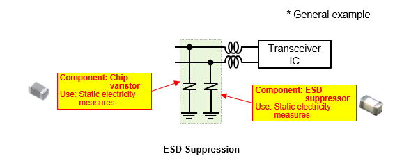
Transceiver I/F
As shown in the figure, a transceiver circuit uses two lines to communicate with external devices (CAN, Ethernet, etc.). Care must be taken for static electricity and noise for the circuit. This is because when static electricity or noise enters from the communication line, this can lead to the failure of electronic components in the worst case. In general, a chip varistor and ESD suppressor are used to prevent static electricity.
Static electricity measures ―― Chip varistor, ESD suppressor
POINT- ❶ Contributes to the suppression of electrostatic (ESD) noise while maintaining circuit communication quality with a lineup of products having a wide range of capacitance characteristics.
- ❷ Chip varistors support low to high communication speeds with capacitance characteristics ranging from 8 to 250 pF.
- ❸ ESD suppressors support high-speed communication speeds with their capacitance characteristics of 0.1 pF.
Summary
As the level of autonomous driving improves and the number of vehicles increases, the number of cameras installed in vehicles is expected to increase. Moreover, there is also a demand for improved performance of the sensing function of cameras. When trying to process a large amount of image data acquired from cameras, losses in electronic components increase accordingly. In the future, automotive electronic components will be required to have "high current," "low losses," "high frequency operation," and "small sizes." Aiming for camera applications, Panasonic Industry offers a wide product lineup of devices equipped with functions required in the future (Table 4).
| Components | Features | Large current | Low loss | High frequency | Miniaturization | High precision |
|---|---|---|---|---|---|---|
Conductive polymer hybrid aluminum electrolytic capacitors |
Low ESR High-reliability |
✔ | ✔ | ✔ | ✔ | |
Automotive power inductor  |
High current, low loss High-reliability |
✔ | ✔ | ✔ | ✔ | |
Chip resistors(high-precision chip resistors) |
High-precision, high heat resistance | ✔ | ✔ | |||
Chip varistors |
Miniaturization and weight reduction | ✔ | ||||
ESD suppressors |
Low capacitance Ultra high-speed data I/F |
✔ | ✔ |
Related product information
Related information