2023-10-31
Application
Technical information
What Is LiDAR in Autonomous Driving Technology?
– Points to Consider in Achieving High-Performance Sensing Function –
LiDAR (light detection and ranging) is a type of sensor using a laser beam. LiDAR emits a laser beam over a wide area and then precisely measures the time that the laser beam takes to return to the LiDAR after hitting and being reflected by an object. A combination of the direction in which the laser beam is emitted and the time the laser beam takes to return to the LiDAR gives the LIDAR the distance to an object. By repeating measurements with various directions of laser emission, the LiDAR is able to recognize the object. This is a technology essential to autonomous driving cars. It is expected that autonomous driving cars equipped with the LiDAR will increase year after year. This article will discuss the functions and system configuration of the LiDAR and will introduce the electronic components making up the LiDAR as well.
What is LiDAR?
LiDAR (light detection and ranging) refers to a sensing technology that is used to measure the time a laser beam emitted on an object takes to return to the LiDAR after being reflected by the object. The LiDAR incorporated in ADAS, AD systems, etc., is used in many cases to sense an object present in the surrounding area. In these systems, the LiDAR is used in combination with cameras, radars, sonars, etc. The LiDAR is operated by several types of optical axis varying methods (Table 1).
| Optical element | Optical axis varying method | Type | Scanning |
|---|---|---|---|
| LD, PD | Mechanical method | Rotation by a motor | A number of LDs and PDs are rotated by a motor to scan the whole area. |
| Polygon mirror | Respective optical axes of a single LD and a single PD are varied by a polygon mirror in scanning. | ||
| Non-mechanical method (solid-state) | MEMS mirror | Respective optical axes of a single LD and a single PD are varied by a MEMS mirror in scanning. | |
| Phased array | Respective optical axes of a single LD and a single PD are varied by a waveguide in scanning. | ||
| Flash | Light from a light source, such as an LED, is emitted over a wide area, and reflected light is collectively scanned by an array of PDs. |
Method of distance measurement and object recognition
Distance measurement and object recognition are carried out using the following methods.
<Distance measurement>
A laser diode emits a laser pulse onto an object and a photodiode receives reflected laser light from the object. The distance to the object is determined based on the time between the point of light emission and the point of light reception.
<Object recognition>
Directions in which laser pulses are emitted and distances measured are plotted into a point cloud image. Using this image, the type of individual or object is identified. A point cloud refers to a set of points representing positional information on an object.
Using LiDAR
In-vehicle LiDAR is used mainly for the following three purposes.
Obstacle recognition
Recognize an obstacle from an obtained point cloud image.
Creating a dynamic map
Combine point cloud data with three-dimensional map data to create the dynamic map required for autonomous driving.
Grasping and correcting the vehicle position
Grasp the traveling position of the vehicle, an obstacle present in the surrounding area, etc., using the dynamic map, and correct the current position to a normal traveling position.
Trends in the LiDAR market
As autonomous driving cars grow in number and the level of autonomous driving improves further, cars equipped with LiDAR are expected to increase. The higher level of autonomous driving leads to a demand for LiDAR's sensing function with higher performance. Functions/performance that electronic components making up the LiDAR are required to offer in the future "higher power," "faster communication," and "smaller in size and weight." Details of these requirements are as follows.
●Higher power
Improving the precision of obstacle recognition requires that the obtained point cloud group be of finer points. When the amount of data processing increases due to higher resolution, power consumption within a semiconductor device, such as the main CPU, increases as well, thus supplying higher power to said semiconductor device is essential.
●Faster communication
Increasing data crunching creates a demand for high-frequency and high-speed transmission/processing capability.
●Smaller in size and weight
In addition to the above challenges, there is a need for reducing the size of electronic components.
System configuration of LiDAR
Overall configuration
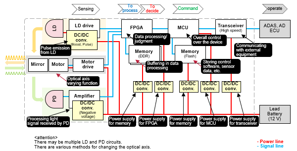
A LiDAR system is composed of the following components. Fig. 1 shows the configuration of a LiDAR system.
●Laser diode: A laser diode generates a high-speed pulse current, emitting a laser beam pulse with a constant waveform and phase.
●Photodiode: A photodiode turns light into an electric signal. When receiving light, it generates a current and voltage. An amplifier is incorporated into a photodiode light-receiving circuit to amplify the output voltage from the circuit.
●FPGA: An FPGA is an integrated circuit that, even after being built into a product, can be reprogrammed to configure an intended logical circuit.
●MCU (microcomputer): An MCU gives a control instruction to an external ECU.
●Transceiver: A transceiver is a device or circuit that communicates with external equipment.
●Memory (DDR): A DDR is used as a buffer during data processing.
●Memory (flash): A flash memory stores control software and sensor data.
●DC/DC converter: A DC/DC converter converts a voltage from a battery into a voltage each electronic component or circuit needs.
Individual circuits and components
DC/DC converter
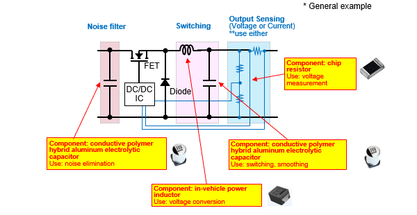
In a DC/DC converter circuit, in general, a conductive polymer hybrid aluminum electrolytic capacitor is used to eliminate noise at the input end and to smooth voltage output at the output end, an Automotive power inductor is used for voltage conversion, and a chip resistor (high-precision chip resistor) is used for voltage measurement.
Noise elimination, switching, and smoothing ―― Conductive polymer hybrid aluminum electrolytic capacitor
POINT- ❶ An inductor made of a metal magnetic material suffers less power loss and carries a large current, contributing to a reduction in the size of the circuit and an increase in the power capacity (low voltage and large current) of the circuit.
- ❷ Having capacitance characteristics to cut off high-frequency components, the capacitor eliminates a wide range of high-frequency noise that is generated by the high-frequency switching of the circuit.
Voltage conversion ―― Automotive power inductor
POINT- ❶ An inductor made of a metal magnetic material suffers less power loss and carries a large current, contributing to a reduction in the size of the circuit and an increase in the power capacity (low voltage and large current) of the circuit.
- ❷ Having loss characteristics in a higher frequency range (low ACR), the inductor contributes to the suppression of power loss caused by high-frequency switching of the circuit.
Voltage measurement ―― Chip resistor (high-precision chip resistor)
POINT- ❶ A chip resistor with a thin-film structure offers a small resistance tolerance and a low TCR, contributing to high-precision control of the output characteristics of the circuit.
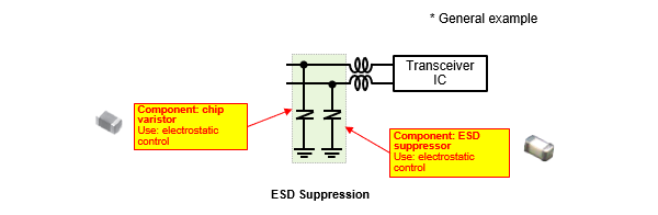
Transceiver I/F
As shown in Fig. 3, a transceiver circuit communicates with external equipment (CAN, Ethernet, etc.) through two lines. To run this circuit normally, you need to be careful with static electricity and noise. Static electricity or noise entering the circuit through the communication line affects the circuit and in a worst-case scenario, may cause its electronic component to fail. Usually, therefore, the circuit is provided with a chip varistor and an ESD suppressor serving as electrostatic control measures.
Electrostatic control ―― Chip varistor、ESD suppressor
POINT- ❶ With a wide range of capacitance characteristics, these components suppress electrostatic noise (ESD) while keeping the communication quality of the circuit intact.
- ❷ With its capacitance ranging from 8 pF to 250 pF, the chip varistor operates effectively at low and high communication speeds.
- ❸ With a capacitance of 0.1 pF, the ESD suppressor operates effectively at high communication speed.
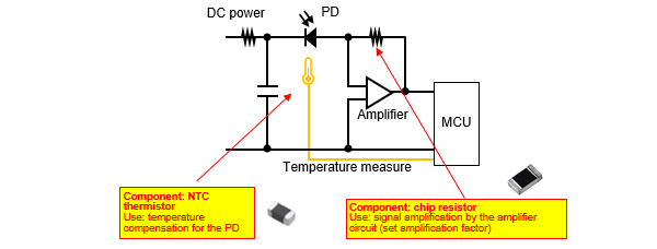
Photodiode light-receiving circuit
A photodiode outputs a current that is proportional in intensity to incoming light. Reflected laser light is weak and therefore needs to be amplified through an amplifier circuit. To construct an amplifier circuit with high precision, the circuit needs a high-precision chip resistor and a thermistor that compensates for temperature-dependent characteristic changes.
Signal amplification by an amplifier circuit (set amplification factor) ―― Chip resistor (high-precision chip resistor)
POINT- ❶ A chip resistor with a thin-film structure offers a small resistance tolerance and a low TCR, contributing to high-precision control of the output characteristics of the circuit.
Temperature compensation for a received light signal ―― NTC thermistor (chip type)
POINT- ❶ A thermistor is small, highly resistant to heat, and is formed by an original technique that offers high reliability, thus contributing to highly precise temperature compensation in the circuit.
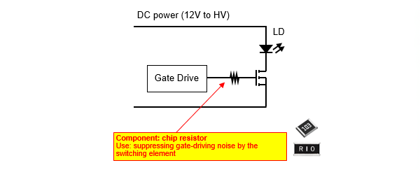
Laser diode irradiation circuit
This irradiation circuit is simply composed of a laser diode, an FET (GaN), and a gate resistance. Because it emits large pulse currents at high speed, the FET (GaN) needs to be precisely switched on/off. Also, it is important to suppress switching noise caused by the FET (GaN). For that purpose, a gate resistance capable of handling a high-power operation must be used.
Suppressing gate-driving noise by the switching element ―― Chip resistor (small and high-power chip resistor)
POINT- ❶ With its original resistance pattern, electrode structure, etc., the chip resistor is small in size and yet handles high-power operations, thus contributing to a reduction in the size of the circuit.
Summary
As autonomous driving cars grow in number and the level of autonomous driving improves further, cars equipped with LiDAR are expected to increase. The higher level of autonomous driving has led to a demand for LiDAR's sensing function with higher performance. Sensor devices incorporated in cars, such as LiDAR, will increase in number and under no circumstances will not decrease in number. There is no doubt that electronic components used in such devices and circuits adjacent thereto will face these demands: "low loss," "large current," "high frequency," and "small size." Panasonic Industry offers a wide variety of product lineups for use in LiDAR (Table 2).
| Component | Feature | Large current | Low loss | High frequency | Small size | High precision |
|---|---|---|---|---|---|---|
Conductive polymer hybrid aluminum electrolytic capacitor |
Low ESR High reliability |
✔ | ✔ | ✔ | ✔ | |
Automotive power inductor  |
Large current, low loss High reliability |
✔ | ✔ | ✔ | ✔ | |
 |
High precision, high resistance to heat | ✔ | ✔ | |||
Chip varistor |
Small and light | ✔ | ||||
ESD suppressor |
Low capacitance Ultrafast data I/F |
✔ | ✔ | |||
NTC thermistor (chip type)
 |
Small, high resistance to heat | ✔ | ✔ |
Related product information
Related information