2023-03-07
Automobile trends and issues
Technical Information
Automotive Trend into the “CASE” Era and Technology Issues (3) - Automated Driving and Recognition Engine -
Download this article
![]()
A third issue on the topic of Automotive Trend into the “CASE” Era and Technology Issues (3), we explore Automated driving, currently in progress for development and verification tests toward practical use, and recognition engines for operating “recognition” of the automated driving.
Automated-driving Function Now in Progress of Development and Verification Test
Practical use of automated-driving function is just ahead of us. The milestone of practical use was the Tokyo Olympic and Paralympic Games held in July 2021. Automated-driving vehicles (Level 4) was introduced for transfers (circling routes) in the athlete’s village, and a variety of verification tests were carried out for automated-driving (Level 4) near Haneda airport and the new Tokyo waterfront area.
Several levels of automated driving have been defined, and 6 levels are defined as “SAE J3016” by the Society of Automotive Engineers (SEA) and widely used (Table 1). (In Japan, similar definition has been published by the government, “Public and Private ITS Initiative and Roadmap 2019”)
Detecting an obstacles in front of and assisting braking, so-called ADAS (Advanced driver assistance systems), generally corresponds to Level 1. In addition, Level 2 functions such as simultaneous activation of adaptive cruise control and automobile lane maintenance have already been set in practical use. Cars equipped with Level 3 functions have emerged, but due to obstacles in legal preparations, they are not on the market for sale in Japan.
| Driver’s role | Function | Function example | |
|---|---|---|---|
| SAE Level 0 | A driver always operates the vehicle, but while the support function is in operation, a driver’s foot may leave the pedal, or hands may leave the steering wheel. | Warning or temporary assistance only | Automatic urgent braking, dead angle warning, off-lane warning, etc. |
| SAE Level 1 | Assistance for either accelaration/deceleration or steering | Lane-keeping and adaptive cruise control | |
| SAE Level 2 | Assistance for both accelaration/deceleration and steering | Simultaneous operation of lane-keeping and adaptive cruise control | |
| SAE Level 3 | The driver’s intervention is not required (Only in level 3, intervention is applied when requested by the system) | Automated driving under limited conditions, operation not permitted unless all the conditions are in place. | Auto-following cruising during congestion, etc. |
| SAE Level 4 | Unmanned taxi in a specific area, etc. | ||
| SAE Level 5 | Automated driving under any condition | Unmanned taxi in any area, etc. |
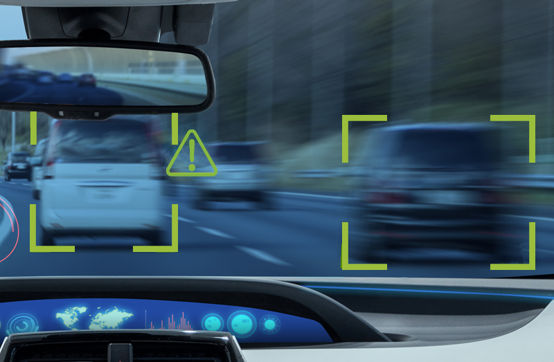
Camera, Radar, and LiDAR work as the principal sensors.
ADAS and automated driving are achieved by three main functions: (A) Recognition, (B) Judgment, and (C) Operation (the same applies to driving by a human driver).
Of these elements, the sensors and recognition engine (recognition processor) are responsible for (A) Recognition, which appropriately recognizes oncoming pedestrians, bicycles, and vehicles, parked vehicles, obstacles, traffic lanes, marks and signs, and traffic signals, as well as passing vehicles in the back and side, vehicles traveling side by side in neighboring lanes, and provides information for the next-step judgment functions.
As sensors, cameras, radars, LiDAR, etc., are utilized.
Camera
Cameras include monocular cameras, stereo cameras (binocular) for obtaining depth information from parallax, and trinocular cameras that combine a stereo camera with a monocular camera for different focal distances. Briefly speaking, sensing accuracy increases by the order of listing, but cost also increases at the same time.
Even with a monocular camera, when the vehicle is in motion, the disparity between one frame and the subsequent frame will reveal the distance of a pedestrian or object. For this reason, a cost effective monocular camera is often still used even now.
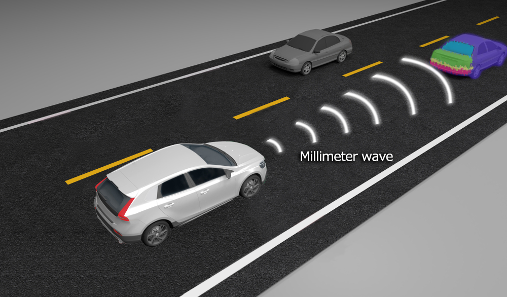
Radar (RADAR : RAdio Detection And Ranging)
Radar is a technology that emits millimeter waves or microwaves and senses the distance and position of humans and objects in the vicinity from their reflections. Several years ago, 24-GHz radar was expected to play the main role, but due to the narrow bandwidth of around 200 MHz caused by restrictions on radio band allocation, attention has turned to the 77-MHz band, where a bandwidth of about 4 GHz is available and antenna modules can be made compact. Recently, solutions based on the low-cost CMOS process have been introduced, and will surely become mainstream in the future.
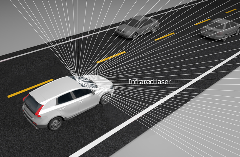
LiDAR (“Light Detection and Ranging” or “Laser Imaging Detection and Ranging”)
LiDAR is radar using infrared laser instead of radio waves. With a shorter wavelength than radio waves, it provides higher resolution, but it presents a problems in weather conditions such as rain and fog.
Because each sensing method has its advantages and disadvantages (Table 2), “sensor fusion method” is also used by fusing two or more technologies. For example, a high class vehicle equipped with the most advanced features exceeding level 2 is said to use a total of 8 cameras and 5 radars, etc., in the front, side and back.
| Camera | Radar | LiDAR | |
|---|---|---|---|
| Resolution | 〇 | △ | 〇 |
| Distance resolution | △ | 〇 | 〇 |
| Bad weather | △ | 〇 | △ |
| Night-time | △ | 〇 | 〇 |
| Other | Human confirmation of images facilitates evaluation and gives low cost. | 77-GHz band is becoming mainstream | Still high cost at present time |
Recognition Engine Structured with Image Processing Accelerator and Inference Unit
The recognition engine or image recognition processor recognizes circumstances in front of and around the vehicle based on the information (image information) from sensors such as cameras. Dedicated ASSP and SoC are already available in the market, but general-purpose FPGAs and GPUs are sometimes utilized. In particular, FPGAs which enable rewriting the internal logic circuit are suited for algorithm verification in prototyping.
The recognition engine consists of a variety of image processing accelerators around a high performance processor core (Fig. 4). Examples include affine transformation accelerators to perform image rotation and expansion/contraction, edge detection accelerators required for white line recognition, and histogram accelerators for obtaining image brightness distribution.
In order to assure safety, the recognition processing must be finished within the time limit defined by the system, and the result must be given to the judgment system in a later stage. For this reason, each process is executed, not in serial, but in parallel.
Performance of the memory system connected to the recognition engine is also important, and high-speed memory such as DDR2 or DDR4 are generally used.
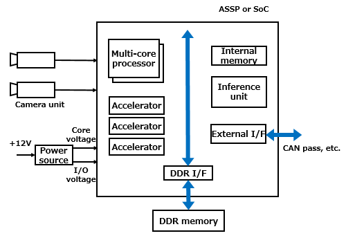
Further, a deep learning inference unit is also loaded in recent years. By combining the traditional matching technique, higher recognition is being aimed to achieve.
In a variety of countries and regions, climate conditions, and road conditions, enormous volume of camera images and radar images are collected and supplied to the high performance deep learning system (cloud, etc.) to construct a neural network model, which is then implemented as an inference unit in the recognition engine. However, because a high accuracy inference unit requires many logic circuits, light-weight design and ingenuity, including bit quantity reduction and pruning, are the key points.
- High-temperature operation warranty and suppression of heat generation are key
When implementing a system (ECU: Electronic Control System) consisting of a camera unit and recognition engine, etc., a caution point is temperature. High-speed processing of an enormous volume of data increases power consumption, and component heat generation makes the entire ECU (Electronic Control Unit) have a high temperature. This ECU is often installed near the room mirror for front monitoring purpose. Particularly under summer sunshine, a vehicle’s compartment reaches high temperatures, but the ECU needs to correctly operate even in such conditions.
Electronic components with superior temperature characteristics and a wide temperature range, such as grade 0 or grade 1 specified by AEC (Automotive Electronics Council) introduced in “Basic Knowledge of Power Circuit (4)” need to be selected.
To suppress temperature rise, reduction of power consumption of the ECU itself is also important. The higher the performance of the recognition engine, requirement for more complex logic and power consumption will be grater, therefore, a balanced solution needs to be selected. In addition, when selecting passive components, cameras (image sensors) and DDR memory used for peripheral circuits, power consumption also needs to be taken into consideration.
- Low-voltage large-current power supply circuit is becoming essential
Caution is also required for power supply. As the process nodes of the recognition engine is scaled down, the core voltage is becoming low around 1.0 V. If we assume the power consumption is 10 W, a power supply circuit needs to handle an output of 1.0 V/10 A. Since a lower rated voltage will result in a more narrow allowable voltage range, a stable power supply circuit without fluctuations is required.
As in-vehicle equipment, caution is required for electro-magnetic noise. When noise is superimposed on a camera image or radar image, incorrect recognition may be included. In addition to properly selecting the switching frequency of the switching power supply (DC/DC converter), it is necessary to minimize the area of the current switching loop (hot loop) where the current switches along with the switching operation. In addition, sensor output wiring including image sensors and analog front end requires implementation that is not easily affected by external noise.
Although a human driver assumes responsibility up to Level 2, the system assumes cruising control in Level 3 or higher. Even when a failure (defect) occurs in the circuit or power supply, safety needs to be maintained securely by using, for example, a redundant (duplicated) power supply system.
Further Utilization of Deep Learning Will Push Automated Driving Forward
Although legal systems and social consensus issues still need to be cleared, there is no doubt that automated driving functions of Level 3 or Level 4 will be put to practical use in the near future. In addition to further improving the existing technologies such as pattern matching, deep learning will surely be one of the key technologies in realizing this goal.
On the other hand, from the viewpoint of electronics, the challenge will be to achieve both high performance and low power operation for recognition engines and sensing systems. Increasing performance generally increases power consumption and heat generation, and accelerates battery power consumption. How to balance performance and operating power will become a key point.
Related product information
Free download of documents
Automotive Trend into the “CASE” Era and Technology Issues
This is a material that summarizes the articles on automobile trends and technical issues published in the technical information of "Optimal Solutions for Circuit Design".
Go to download »