Automotive Trend into the “CASE” Era and Technology Issues (2)
- Battery Management System -
2019-12-16
- Lithium-ion Batteries that Accelerated Commercialization of Electric Vehicles (EV)
- Battery Management System (BMS) - Essentially Required for Safe Charge/discharge Control
- Method of estimating charged condition (SOC) of the battery pack
- Maximizing Battery Performance by Balancing Control
- Continue Attention to an Evolving BMS
- Related product information
- Tags related to this article
The second issue of the Automotive Trend into the “CASE” Era and Technology Issues, we explore the topic of electric vehicles (EV) under the worldwide shift toward CO2 emission suppression, by focusing this time on batteries and battery management systems (BMS).
Lithium-ion Batteries that Accelerated Commercialization of Electric Vehicles (EV)
Electric vehicles have been developed through targeting driving performance and cruising range comparable to that of gasoline or diesel-driven vehicles. While a variety of technological developments are pushing EVs forward, lithium-ion batteries, having volume-energy density and weight-energy density several times higher than those of the traditional nickel-hydrogen batteries, have accelerated commercialization of EVs.
Lithium-ion batteries generally indicate use of lithium transition metal composite oxide for the positive electrode, and carbon material for the negative electrode, but some products use lithium-based oxide for the negative electrode instead of the positive electrode, indicating a variety of combinations already in use.
Although lithium-ion batteries have excellent volume-energy and weight-energy densities, significantly large size batteries were required conventionally for achieving a cruising range comparable to those of gasoline-driven or diesel-driven vehicles. However, at present time, thanks to improvements not only in battery performance but also in power semiconductor efficiency, even compact EVs can now achieve a cruising range of over 400 km (WLTC mode).
Battery Management System (BMS) - Essentially Required for Safe Charge/discharge Control
Assuming the role of extracting battery performance installed in EVs - Battery Management System (BMS). A unit composed of electronic circuits and software equipped mainly with the following functions.
- Detection of excessive voltage, excessive current, abnormal heat generation, etc., and shutdown control
- Charge control and estimation of remaining battery life (SOC=State of charge) used in calculating the remaining cruising range
Because a lithium-ion battery may lead to abnormal heat generation by charging beyond the full voltage, or discharging beyond the final voltage, accurate detection of the SOC is essential for safe charging/discharging control.
In addition, BMS assumes the following functions as an option.
- Cell-balancing control for maximizing battery pack capacity by unifying the charged condition of battery cells
Of the items shown above, one of the basic functions of BMS, 2), is explained below.
Method of estimating charged condition (SOC) of the battery pack
In the case of gasoline or diesel-fueled vehicles, fuel liquid surface in the fuel tank can be physically identified by the float height, but in the case of EVs, it is not possible to know externally how much energy is stored in the battery pack, so “estimation” is required by using a dedicated circuit and algorithm.
To know the SOC, there are 2 main methods.
(a) Method of measuring voltages of battery cells
(b) Method of accumulating battery-pack input-output current
(a) Method of measuring voltages of battery cells
(a) Method of measuring voltages of battery cells
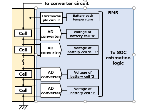
First, we will explain the method of knowing the SOC from cell voltage (Fig. 1).
The voltage between the 2 terminals of each battery cell that forms a battery pack is read using an AD converter then give to the SOC estimation logic. As the cell voltage changes from temperature, measure the temperature of the battery pack and also give it to the SOC logic.
However, preparing the same number AD converters as battery cells is costly and wasteful in terms of implementation, so a multiplexer is placed in front of the AD converter, measuring cell voltages by scanning them at a fixed cycle.
The AD converter for measuring cell voltages does not require a very high speed, but accuracy for several mV is required as mentioned later. Therefore, an ΔΣ type is often used for securing ENOB (effective number of bits) of 10 bits or more relatively easily.
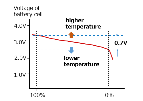
Depending on the material used for positive and negative electrodes, we assume that the voltage at full charging is assumed to be 3.4 V, and the final voltage to be 2.7 V (Fig. 2).
This means that by assuming 3.4 V as 100%, and 2.7 V as 0%, the SOC can be calculated from the cell voltage. In this case, for calculating the SOC with 1% accuracy, the cell voltage needs to be measured with a high accuracy of 0.7÷100=0.007 V (7 mV). In reality, the cell voltage has a temperature coefficient that goes up at higher temperatures and goes down at lower temperatures. Particularly, during cruising and during charging (including regenerative braking), the temperature changes according to the current, and the voltage also fluctuates without stability. Correction can be made to some extent from cell and pack temperatures, but under an unstable condition, maintaining a high measurement accuracy can be very difficult.
Based on these restrictions, when obtaining the SOC by measuring cell voltages, an appropriate margin is often set up (for example, by assuming a measurement error of ±10%, and an actual value of 10% to 90% to display as 0% to 100%, and so forth).
(b) Method of accumulating battery-pack input-output current
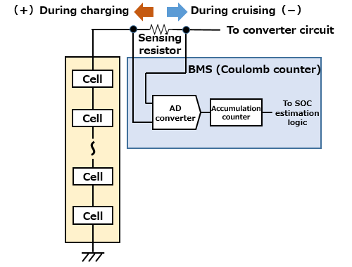
This is the method of calculating the SOC from the charge (energy) estimated remaining in the cell by accumulated current coming into the cell (Fig. 3).
This method is also called the Coulomb counting method. As an example, by assuming the battery pack capacity is 1000 Ahr, and when a charge equivalent of 10.0 Ahr flow is measured as current, the SOC can be calculated as being reduced by 1.00%. On the contrary, when a charge equivalent to 10.0 Ahr is charged, the SOC is calculated as being increased by 1.00%.
A terminal voltage of a sensing resistor (bus bar, etc.) having resistance in the order of μΩ is converted by the A/D converter and accumulated. In order to suppress the accumulation of errors, the effective number of bits needs to be large, and the sampling rate needs to be fast to some degree for the purpose of capturing changes.
However, methods (a) and (b) explained earlier are only theoretical, and in reality, the SOC needs to be obtained also considering deterioration over time (SOH: State of Health). Implementation varies by auto-manufacturer and details are not made open, but we assume that by using the information of the voltage and current measured by the technique shown in Fig. 1 and Fig. 3, the SOC is estimated by using mathematical methods such as the Kalman filter.
In addition, “(1) Detection of excess voltage, excess current, abnormal heat generation, etc., and shutoff control,” as indicated as the basic role of the BMS, can be achieved basically by the extension of the circuit for measuring cell voltages and cell temperatures, and the circuit for measuring the outgoing and incoming current of the battery pack.
Maximizing Battery Performance by Balancing Control
Lithium-ion batteries gradually deteriorate through repeating charging and discharging. If all cells of a battery pack deteriorate equally, there would be few problems, but, in reality, deterioration varies.
In a battery pack, battery cells are connected serially as shown in Fig. 1 or Fig. 3 but we will consider cells in parallel this time as shown in Fig. 4.
When variation is generated in cell characteristics or performance by aging, discharge needs to be stopped when the cell with the least remaining capacity reaches the discharge bottom limit in the discharge mode (bottom left of Fig. 4). This means that the energy in the areas sandwiched by a pair of red arrows in the other cells is not available.
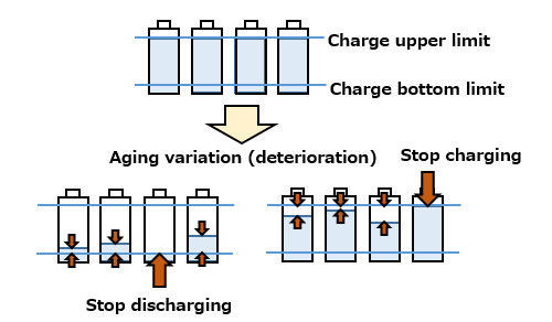
In addition, in the charging mode, when a cell with the highest remaining capacity reaches the charging upper limit, charging operation needs to be stopped (bottom right of Fig. 4). The remaining empty areas sandwiched by a pair of red arrows in the other cells cannot be charged.
This means that effective capacity of the battery pack is reduced by the restriction caused by other cells variations.
Cell balancing is the means for suppressing such variation. As a means for solving this problem, a passive balancing method exists by unifying the SOC to the discharge the bottom limit of each cell by discharging remaining capacity of cells through a resistive load, and active balancing method exists by distributing energy from the cells with a larger remaining capacity to those with less remaining capacity. The control circuit naturally gets complicated in the latter case.
Continue Attention to an Evolving BMS
A part of BMS has been shown schematically in Fig. 1 and Fig. 3, but reality is much more complicated, requiring many components. To achieve a compact size, a variety of BMS ICs and circuit components that integrate these functions have been released by various electronic component manufacturers.
In addition, new control systems including SOC estimation are being developed on a daily basis. The existing concept shown at this time may be classified into “classic method” some day.
Batteries themselves are in progress with R&D for new positive electrode material and negative electrode material and further improvement of energy density is expected.
We cannot divert our eyes from the spread and evolution of the BMS.
The next issue will focus on AI processors as a key for ADAS and automated driving.
Related product information
Tags related to this article

This is a material that summarizes the articles on automobile trends and technical issues published in the technical information of "Optimal Solutions for Circuit Design".
