Example of chip resistor adoption (1)
– Reduction of the number of parts required and improvement of reliability through the adoption of compact, high withstand voltage, high-precision chip resistors –
2022-03-18
- Miniaturization of battery modules and reduction of mounting costs - High-voltage chip resistors used for voltage monitoring in BMSs and high-voltage monitoring circuits -
- Contributing to the miniaturization and longer life of operational amplifier circuits that are used in large quantities
- Related product information
- Related information
- Tags related to this article
The trend of electrification of vehicles, which began in developed European countries to address climate change issues, is now spreading around the world. Some countries have a policy of only allowing the sales of EVs in a few decades, indicating a rapid shift to EVs.
As a matter of course, EVs use battery power to rotate the main motors and generate driving force. Furthermore, battery power not only runs the main motors, but also almost everything that uses electricity, including the steering and power windows, door mirrors, control systems, and communication systems. Although the performance of battery units has improved, the cruising range of EVs is still shorter than conventional vehicles powered by internal combustion engines. Therefore, the role of inverters and Battery Management Systems (BMSs) is considered of utmost importance, where inverters are used to convert DC output from batteries to AC required by drive motors in order to make the most of limited charge capacity. BMSs are adopted to maintain the performance of batteries over the long term by minimizing battery deterioration as much as possible.
Such inverters and BMS circuits use a large number of resistors, which have different required characteristics depending on the application. Panasonic resistors, with excellent features such as high-voltage, high-temperature, and high-precision characteristics, are valued and adopted by customers. This article introduces two examples where customers adopted chip resistors for BMSs.
Miniaturization of battery modules and reduction of mounting costs
- High-voltage chip resistors used for voltage monitoring in BMSs and high-voltage monitoring circuits -
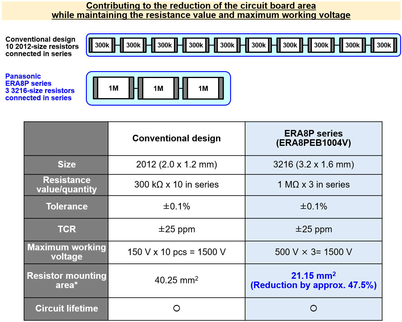
EV batteries are produced by connecting multiple modules that combine small battery cells to achieve a high-voltage output. For example, a customer uses a battery with a maximum working voltage of 1500 V. For the high-voltage monitoring circuit used for monitoring the voltage of the battery's BMS, the customer used 10 2012 size (2 x 1.2 mm) thin-film resistors connected in series with a resistance value of 300 kΩ, and a withstand voltage of 150 V in a conventional design. In order to make improvements, the customer adopted Panasonic's proposal of replacing the previous resistors with the three 3216 size (3.2 x 1.6 mm) thin-film resistors connected in series with a resistance value of 1 MΩ, and a withstand voltage of 500 V (model number: ERA8PEB1004V). As a result, the replacement with Panasonic's thin-film resistors reduced the resistor mounting area on the circuit board to 21.15 mm2, compared to the area of 40.25 mm2 when 10 resistors (2012 size) were used to construct the monitoring circuit, thereby contributing to an area reduction of about 47.5%.
This ERA8P series is extremely accurate, with a tolerance of ±0.1% and temperature characteristics (TCR) of ±25(x10-6/K). Further, this resistor series features design technology that takes the lifetime (total tolerance) into account to maintain accuracy over a long period of time. More specifically, Panasonic's proprietary technology, including the adoption of components and materials that can absorb stress, and design innovations, suppresses solder cracks caused by the difference in the thermal contraction between the circuit board and mounted resistors, one of the major problems that can occur during long-term use. In general, the larger the resistor size, the greater the stress caused by the difference in thermal contraction. However, Panasonic chip resistors have superior connection reliability compared to other companies' products, regardless of thin-film or thick-film type resistors.
The advantage of such a lifetime-oriented design is that the degradation of the resistance value is very small, enabling highly accurate monitoring of the state of degradation of batteries over a long period of time. This can contribute to the detection of signs of EV battery anomalies.
Contributing to the miniaturization and longer life of operational amplifier circuits that are used in large quantities
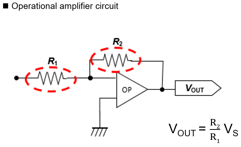
High-precision resistors are used in operational amplifier circuits for boosting the voltage of batteries to the required level. The degree of amplification of operational amplifier circuits is basically determined by the ratio (difference) of two resistors, R1 and R2. Therefore, the resistors require high precision but do not need to provide such a high withstand voltage performance. Accordingly, there are increased cases where EV manufacturers use thin-film resistors with higher precision.
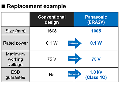
With regard to thin-film chip resistors used in this operational amplifier circuit, Panasonic's "ERA*V" series offers compact products that are one size smaller than competitors' products with the same performance, thereby enabling a reduction of the area of circuit boards. As an example, replacing a resistor with the 1608 size (1.6 x 0.8 mm), a rated power of 0.1 W, and a maximum working voltage of 75 V with Panasonic's 1005 size (1.0 x 0.5 mm) "ERA2V" series thin-film resistor with a rated power of 0.1 W, and a maximum working voltage of 75 V enables a reduction of the resistor mounting area by approximately 60.3%.
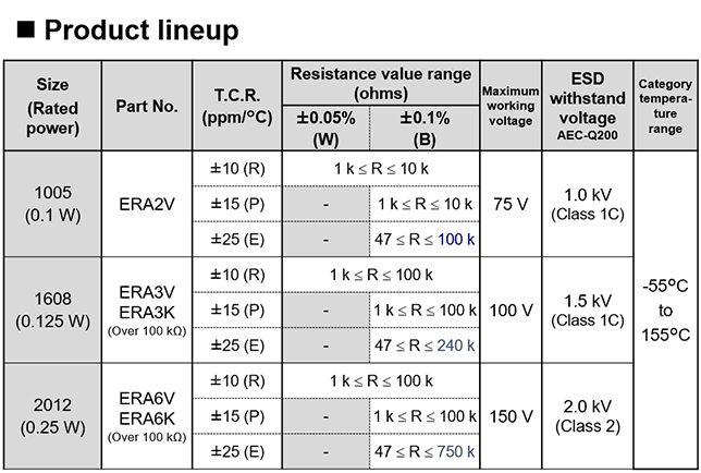
Compared to thick-film resistors, thin-film resistors are generally more vulnerable and susceptible to breakage under conditions such as the application of overload and inrush voltages caused by electrostatic discharge (ESD). However, Panasonic's "ERA*V/K/P" series resistors have been designed with ESD measures, taking into account the level of static electricity, which is approximately equivalent to that humans are charged with (1 k to 1.5 k volts). To be specific, the company guarantees to withstand voltages of 2 kV, 1.5 kV, and 1.0 kV for the 2012 size, 1608 size, and 1005 size products, respectively. These values are the highest in the industry (as of March 2022).
Similarly, Panasonic has taken measures against the drawbacks of thin-film resistors, including solder cracks caused by thermal shock (thermal contraction after mounting) and electrolytic corrosion (sulfidation properties) caused by the penetration of flux used during soldering. The company offers highly reliable and weather-resistant products that can withstand such thermal shock and corrosion. These excellent advantages over conventional products and other companies' products have become possible by reviewing the adopted materials and design.
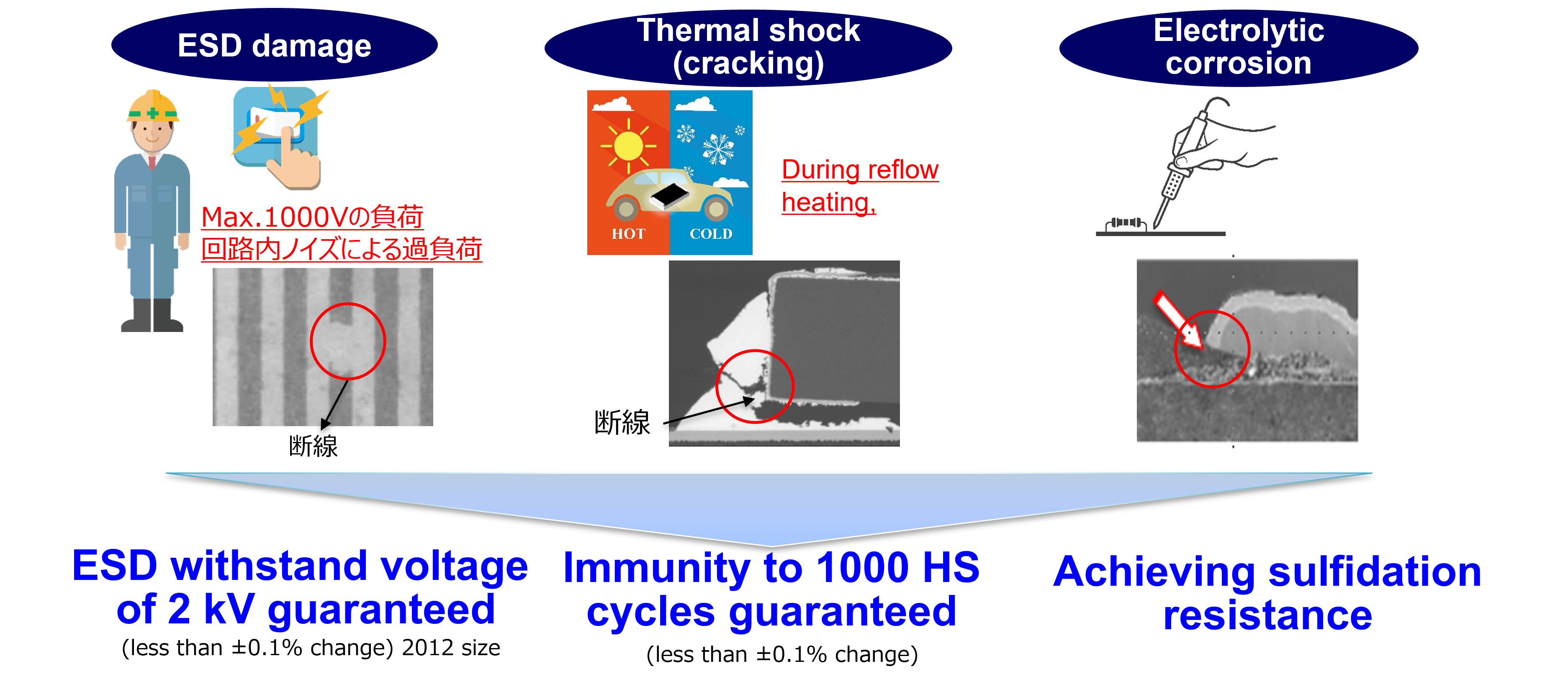
Fig. Advantages of the company's thin-film resistors These thin-film resistors, which combine compact size, high reliability, and high weather resistance features achieved by Panasonic's proprietary technology, will contribute to reduced resistor mounting areas and costs, and improved reliability.
Related product information
Related information
- Basic Knowledge of Resistors
- Chip resistors that are smaller but which provide more advanced functions are now an important component in solving problems.
- Current Detection Chip Resistors for Responding to the Large Current and High Precision Requirements
- High Precision Chip Resistors that Promote High Performance, Safety Improvement, and Energy Saving
- Anti-sulfurated Chip Resistors That Have Achieved High Reliability by Adopting Gold-based Electrodes and High Palladium-Silver Alloy Electrodes
- Chip resistor’s failure phenomenon/mechanism and solutions (1)
- Chip resistor’s failure phenomenon/mechanism and solutions (2)
Tags related to this article

Materials for Example of chip resistor adoption that are posted as technical information in "Optimal Solutions for Circuit Design".
