Maximum Temperature Specification Based on Terminal Temperature
2023-05-19
- Resistors and terminal temperature specification
- Cautionary points to note in temperature measurement using the thermocouple
- Selecting a component for terminal-temperature-based specification and power setting
- Summary
- Reference
- Related product information
- Related information
- Tags related to this article
Growing demand for more apps with higher functions has led to the development of highly integrated circuits and surface-mounted electronic components, which are miniaturized so as to have highly dense packaging structures. High-performance components in compact form suffer a problem from increasing self-heating. As a result, product set design for curbing heat generation for components becomes more complicated and challenging. There is an approach to solving this problem from the side of the components, and we would like to introduce an example of such an approach.
Resistors and terminal temperature specification
Difference between a resistor with leads and a surface-mounted chip resistor in a thermal design concept
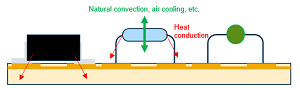
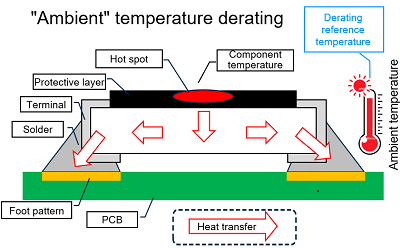
In the past, many components with leads were incorporated into circuits. A resistor with leads releases 80% to 90% of its heat into the ambient space. This means that it is important on how the resistor, which is under the influence of the ambient environment temperature, lets heat escape to the ambient space. For this reason, the rated power of the resistor is guaranteed based on the ambient temperature. This approach is called "ambient-temperature-based specification" and is now generally adopted for the rated power guarantee.
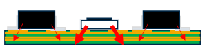
Currently, however, many surface-mounted components, which include resistors, are in wide use. For example, a surface-mounted component, like a rectangular chip resistor, is mounted differently in structure from a component with leads (shown in the left column of Table 1) and is mounted in the state of being in contact with the board (shown in the right column of Table 1).
| Component used | Component with leads | Surface-mounted component |
|---|---|---|
| Heat effect image |
 Resistor with leads |
 Surface-mounted resistor |
| Features |
|
|
Different from a component with leads, the surface-mounted component, which is already affected by the ambient temperature, readily undergoes the effects of heat generated by itself and other components' heat transmitted through the board. This fact should be heeded.
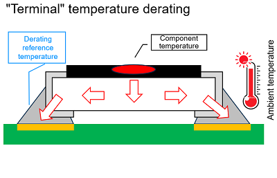
In component designing based on the ambient temperature, accurately calculating a load to the component at the time of load application to the component (operation of the component) is difficult. Out of these circumstances, a new approach has been conceived, at the time of load application, attention is paid to temperature rise at the terminal allowing accurate calculation of a load on the component. Specification for the maximum rated power based on this approach is referred to as "terminal-temperature-based specification" as opposed to "ambient-temperature-based specification," which is the conventional approach.
The trend in standardizing terminal-temperature-based specification
A resistor in operation generates heat by itself due to a load applied thereto. A rise in the temperature of the resistor causes its performance and service life to deteriorate, therefore the resistor must be used with a tolerance in applied power ensured. This approach is called derating. When the ambient temperature is high, the resistor is used with a lower applied power. In this situation, according to the "terminal-temperature-based specification" approach, applied power is set based not on the ambient temperature but on the terminal temperature at the time of load application under the service environment.
There is a movement for establishing this terminal-temperature-based specification as one for international standards, and a group of Japanese manufacturers, including Panasonic, have joined the movement.
Terminal temperature measurement methods and cautionary points
Panasonic has employed terminal temperature measurement methods, referring to "JEITA RCR-2114 Study for the derating curve of fixed surface mount resistors," a technical report issued by the Japanese Electronics and Information Technology Industries Association. Among them are two typical measurement methods: infrared thermography and thermocouple-used measurement.
| Device used | Infrared thermography | Thermocouple |
| Operation principle summary |
The device observes infrared rays emitted from a material and determines the surface temperature of the material, based on the infrared rays. | Respective front ends of different metal wires are brought into contact with each other to create a circuit (thermocouple), and a thermoelectric force generated at the junction of the circuit is measured as the temperature for the measurement target. |
| Advantage | The device is easy to handle and allows a wide range of temperature measurements in a contactless setup. | The device allows temperature measurement with no influence from the ambient temperature. |
| Disadvantage |
|
|
We assume that there will be many opportunities for choosing the thermocouple in actual temperature measurement. Please see the following cautionary points.
Cautionary points to note in temperature measurement using the thermocouple
(1) Types of thermocouples
There are several types of thermocouples, which need to be used separately according to a measurement target material and for a measurement target temperature range. For a component that is small in volume and heat capacity, such as a chip resistor, a K-type thermocouple with low heat conductivity would be a better choice and a thermocouple with a small wire diameter would also be desirable because using these thermocouples would result in less heat transfer to the thermocouples. A T-type thermocouple is superior in terms of preventing temperature measurement error but shows high heat conductivity, thus absorbing heat generated by a measurement target. It could be said, therefore, that it is not fit for a component with a small heat capacity.
| Thermocouple symbol |
Class 1 | Class 2 | ||
|---|---|---|---|---|
| Temperature range | Tolerance | Temperature range | Tolerance | |
| K | -40°C or higher and lower than 375°C | ±1.5 ℃ | -40°C or higher and lower than 333°C | ±2.5 ℃ |
| 375°C or higher and lower than 1000°C | ±0.004・| t | | 333°C or higher and lower than 1200°C | ±0.007 5・| t | | |
| T | -40°C or higher and lower than 125°C | ±0.5 ℃ | -40°C or higher and lower than 133°C | ±1.0 ℃ |
| 125°C or higher and lower than 350°C | ±0.004・| t | | 133°C or higher and lower than 350°C | ±0.007 5・| t | | |
* | t | denotes the absolute value of a temperature (°C) that has nothing to do with the negative and positive signs of measurement temperatures.
Reference source: JIS C 1602: 2015
(2) Processing the front ends of the thermocouple and attaching the front ends to a measurement spot
When using a thermocouple, be careful of the connection where the two wires are connected.
- Because thermocouple works, based on the electromotive force difference between different types of metals, their respective front ends must be in contact with each other. A thermocouple is incapable of temperature measurement unless its front ends are in contact with each other.
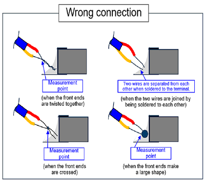
- Weld the front ends of the thermocouple together with a small spot welding machine, etc. Merely twisting the front ends together or soldering them together may result in a failure in the correct measurement of the temperature target spot.
- If the two wires cross at their front ends or the size of the welded front ends is improper, the front ends cannot be fixed at the proper position when soldered to the terminal. The thermocouple measures the temperature at the contact point. If an extra portion of a wire extends beyond the contact point, this extra portion releases heat, thus making temperature measurement unstable. To curb undesired heat release, the front ends of the thermocouple need to be welded properly.
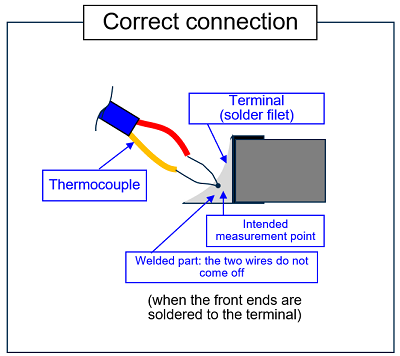
After welding the front ends of the thermocouple correctly, fix the front ends at the center of the terminal solder filet. If the front ends are close to the edge of the filet or are exposed out of the filet, you won’t be able to make accurate temperature measurements.
(3) Temperature correction
Temperature measurement from the thermocouple may contain an error that makes the measurement inconsistent with an actual measurement. The following two problems are considered to be major causes for such an error. Take these problems into consideration before taking measurements.
- The electromotive force of the thermocouple is unstable because of the irregularities of thermocouple manufacturing lots.
- Voltage measurements of a data logger are erroneous because of a measurement error made at each channel.
Selecting a component for terminal-temperature-based specification and power setting
For product set designing and product evaluation, read the above-mentioned JEITA report and heed the cautionary points listed above. See the following description to understand how to read the specified temperatures shown on the datasheet for Panasonic resistor products.
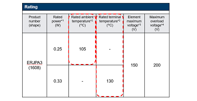
* Example) Surge-resistant fixed resistor ERJPA3 series
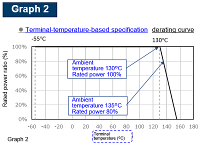
When the datasheet contains two kinds of product ratings, as shown in Fig. 3, adjust applied power according to graph 1 (rated ambient temperature) and graph 2 (rated terminal temperature).
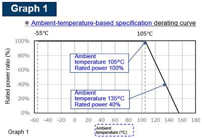
Ex.
When the ambient temperature is 105°C: load power is up to 100% of the rated power
When the ambient temperature is 135°C: load power is up to 40% of the rated power
Ex.
When the terminal temperature is 130°C: load power is up to 100% of the rated power
When the terminal temperature is 135°C: load power is up to 80% of the rated power
Use the product under a condition in which the product temperature is equal to or lower than the category upper limit temperature. If you have difficulty in deciding which of the rated ambient temperature or the rated terminal temperature is to be used, use the rated terminal temperature.
Summary
A surface-mounted component, compared to a component with leads, is more likely to generate heat by itself and to receive heat from components nearby. As components get smaller and packaging structures get denser, an important approach in design/development work has been conceived "terminal-temperature-based specification." For terminal temperature measurement, a thermocouple is used in many cases. To take accurate measurements, understanding well on how to handle the thermocouple is essential. Panasonic provides a data sheet listing rated terminal temperatures. We advise you to use the datasheet for circuit design work.
Reference
- Study for the derating curve of fixed surface mount resistors (JEITA RCR-2114)
Related product information
Related information
- Chip resistor’s failure phenomenon/mechanism and solutions (1)
- Chip resistor’s failure phenomenon/mechanism and solutions (2)
- Example of chip resistor adoption (1)– Reduction of the number of parts required and improvement of reliability through the adoption of compact, high withstand voltage, high-precision chip resistors –
- Example of chip resistor adoption (2)
Tags related to this article

Materials forMaximum Temperature Specification Based on Terminal Temperature that are posted as technical information in "Optimal Solutions for Circuit Design".
