Basic Knowledge of Power Circuits (4)
- Points to Note When Designing a Power Circuit for an ECU -
2019-10-18
In this article, which is the last in this series of lectures that provide a basic knowledge of power circuits, we are going to discuss major points to note when designing a power circuit as part of an electronic control unit (ECU) of a car.
One car carries some tens of ECUs.
The electronization of cars has developed steadily, and cars are now being manufactured with more and more electronic equipment. Today, cars are equipped with powertrain control systems for controlling the engine and transmission, vehicle control systems for controlling suspension and brakes, body control systems for controlling door locks and meters, and information communication control systems for controlling car navigators and telematics. In addition, cars equipped with advanced driver-assistance systems (ADAS) have become widespread in recent years. It is said that currently, one car carries some tens of ECUs, and the number of ECUs incorporated in each car is expected to increase further in the future.
Fig. 1 depicts the overall configuration of an ECU. The ECU is roughly composed of an input interface that handles digital signals and analog signals from sensors; an output interface that drives actuators and lamps; a bus interface, such as a CAN bus, that exchanges information with other ECUs; a microcomputer or dedicated processor that controls the whole processes; memory storing control programs and data; a power circuit; and a protection element. In a different ECU, these components may be different in their specific functions.
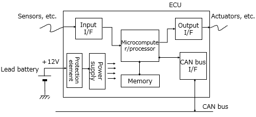
Let's look at the power supply. The power supply converts +12 V DC voltage, which is outputted from the lead battery, into a low voltage ranging from about 1 V to 3.3 V, which the microcomputer and memory need. Since the voltage input to the ECU should be larger than the voltage coming out of the ECU, a stepdown-type switching power supply, which is described in "Basic Knowledge of Power Circuits (2)" and "Basic Knowledge of Power Circuits (3)," is the proper power supply to be incorporated into the ECU.
It should be noted, however, that since the power supply of the ECU must meet the car's specific requirements, a power circuit for industrial equipment and consumer products cannot be used as the power supply for the ECU. Now let's take a close look at some points to note for design work.
+12 V voltage that fluctuates widely
+12 V voltage from the battery, which is a voltage input to the ECU, may seem to be stable. Actually, it is not stable and fluctuates widely. Such unstable behavior is referred to as cold cranking and load dump. Measures for protection from a reverse cable connection are also needed.
Cold cranking
This phenomenon refers to when the starter, which consumes a large amount of current, is turned while the battery and engine are still cold, causing a voltage of +12 V to drop to about +3 V (see Fig. 2).
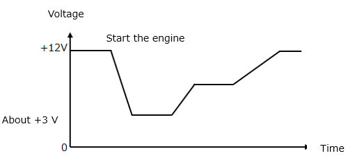
The stepdown-type switching power supply becomes incapable of maintaining its regulation operations when an input voltage to the power supply drops lower than the output voltage from the power supply. For example, suppose the input voltage drops to +3 V because of cold cranking. In this case, a power circuit with an output voltage of +1.8 V or +2.5 V can continue its operations but a power circuit with an output voltage of +3.3 V cannot.
There are two solutions to this problem. One is to temporarily stop the ECU including the power circuit when the +12 V voltage drops below a given threshold. This method is applicable to an ECU not directly related to the traveling function, such as a car audio ECU. Another is to adopt a boosting-type switching power supply in place of the stepdown-type so that the ECU can continue its operations even if the +12 V voltage drops.
Load dump
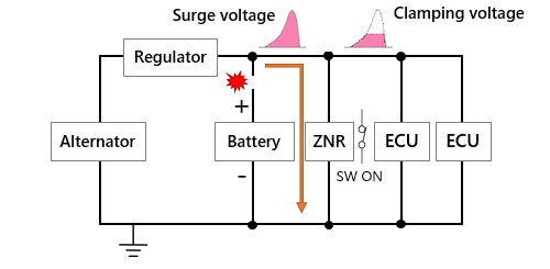
When a battery cable is broken or has a contact failure while the alternator is generating power, a +12 V voltage may rise up to some tens of volts. This phenomenon is referred to as load dump.
It is said that load dump voltage reaches 40 V or so and, in some cases, even exceeds 100 V. To be protected against such an extreme voltage, the input side (primary side) of the power circuit of the ECU must be provided with a protection element, such as a ZNR surge absorber, that clamps an overvoltage. Obviously, estimating the withstand voltage of an input capacitor of the ECU at +12 V does not work in actual situations. Such a component needs a voltage rating equal to or higher than the clamp voltage of the protection element (see Fig. 3).
Protection from a reverse cable connection
When positive and negative cables are mistakenly connected to the wrong negative and positive terminals of the battery, such as during maintenance work, a -12 V voltage may be applied to the ECU. To protect the ECU from damage caused by the reverse cable connection, it must be provided with a means of protection. Perhaps this kind of mistake rarely happens when handling ordinary equipment, but it could happen when someone works on a car for maintenance. The person who tinkers with the car may be a professional or might not be, and in the latter case, there is a possibility for error.
Generally, a Schottky barrier diode is used as a means of protection against reverse cable connection. It should be noted, however, that this diode allows a forward voltage of about 0.4 V and therefore reduces battery voltage to about +11.6 V, and that a leak current from the diode results in energy loss, causing heat generation. Recently, an "ideal diode" has appeared in the industry as a solution to these problems. It is a protective diode whose forward voltage is reduced to almost zero using a MOSFET.
Meeting environmental conditions in which cars are used
When designing the power supply for the ECU, you must take into consideration various environmental conditions.
Operation temperature range
Cars are used in every corner of the world, running in extremely cold regions and desert areas as well. Automotive equipment, therefore, must be able to operate at both low and high temperatures with sufficient margin.
The automotive electronics council (AEC) defines standard operating temperature ranges of automotive equipment, specifying temperature-reliability grades for each standard (see Fig. 4).
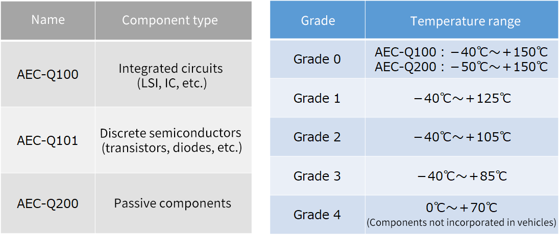
An ECU housed in the engine compartment, which is the hottest part of the car, must be composed of grade 0 or 1 components. An ECU built in the vehicle interior or trunk where the rise in temperature is not so intense, on the other hand, may be composed of grade 3 components and cause no problem at all.
As described in "Basic Knowledge of Power Circuits (3)," you need to confirm that passive components, such as capacitors and inductors, offer the desired characteristics in the whole environmental temperature range. To know about heat suppression measures, see "Basic Knowledge of Heat Suppression Measures."
Interference with AM radio
As described in 「"Basic Knowledge of Power Circuits (3)," the switching power circuit emits EMI noise, which originates from a loop (hot loop) in which current flows and stops alternately. Although the ECU board is housed in a metal enclosure that serves also as a shield, a noise leak from its connector cannot be neglected. Noise generation, therefore, should be suppressed as much as possible in the circuit design stage.
A major problem to deal with is interference with AM radio (medium wave band). As its name implies, an AM (amplitude modulation) radio wave is a wave modulated in amplitude, and noise superposed in such a wave is reproduced as a noisy sound. In Japan, a frequency band ranging from 526.5 kHz to 1606.5 kHz is allocated to AM radio broadcasting. This frequency band allocation leaves us with 1.8 MHz or 2 MHz as the best choice for setting the switching frequency.
We have standards for tests on radio interference in a vehicle, such as interference with radio equipment. CISPR 25 is set by the international electrotechnical commission (IEC) as such standards to be applied to radio interference tests.
Long-term Reliability and Availability
A car is used for over 20 years in some cases. To endure such a long period of service, individual components making up the ECU need to be of extremely high quality with fewer initial failures or random failures.
From the viewpoint of long-term maintenance of the car, it is also important that the components remain available for a long period. Besides these requirements, selecting a passive component requires extra caution in order to know how its characteristics deteriorate over a long period of service.
In addition to the issues mentioned above, there are other issues to clear. One is difficulty in securing a mounting space for the ECU, which has come to our attention as equipment electronization advances and prompts us to push for miniaturization of power circuits. Another issue is the extension of the traveling distance of electric vehicles, for which energy loss in the power circuit must be reduced to the minimum. In this manner, we have to clear various issues.
Still, there is no doubt that car electronization will advance further and that the ECU market will continue to grow significantly.
This is the last article in this series of lectures providing a basic knowledge of power circuits. We will describe a trend of automotive electronics in a new series of lectures.
Related product information
Tags related to this article
This document summarizes the Basic knowledge of power supply circuit posted as technical information for the Optimal Solutions for Circuit Design.
