Zoom
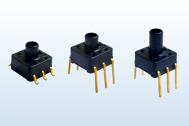
Pressure sensor Built-in amplifier compensation circuit.
Overall accuracy : ±1.25 % FS (Standard), ±2.5 % FS (Low-pressure type)
Overall accuracy : ±1.25 % FS (Standard), ±2.5 % FS (Low-pressure type)
Pressure type
・Standard type(with glass base) : Rated pressure ±100 kPa to 1000 kPa
・Economy type(without glass base) : Rated pressure 40 kPa
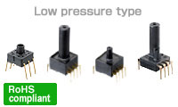
・Low pressure type : Rated pressure 6 kPa
・Standard type(with glass base) : Rated pressure ±100 kPa to 1000 kPa
・Economy type(without glass base) : Rated pressure 40 kPa
・Low pressure type : Rated pressure 6 kPa
Compact size, space-saving
Compatible size for PS type (Standard / Economy, S and M packages)
Compatible size for PS type (Standard / Economy, S and M packages)
Topics
- 2025-11-04 PS-A series have been discontinued.
- 2023-11-21 PS-A series is NOT Recommended for New Design.
- 2023-03-31 Some parts of PS-A Pressure Sensors has been discontinued.
- 2021-04-01 Some parts of PS-A Pressure Sensors are Not Recommended for New Design (5 part numbers).
- 2016-10-28 Registration certificates of quality and environment certifications (ISO, TS) are available for download
Basic Information
Pressure sensor Built-in amplifier compensation circuit. PS-A P Package release!
Features
-
Contains built-in amplification and temperature compensation circuit. Circuit design and adjustment
-
High-level precision and high reliability realized.
- Overall accuracy is ±1.25% FS (Standard type)
- Overall accuracy is ±4% FS (Economy type)
- Overall accuracy is ±2.5% FS (Low pressure type)
-
Compact pressure sensor unit that saves space.
Same size and as previous PS pressure sensor.
[Footprint]
7.0 mm (W) × 7.2 mm (D) (PS-A)
10.4 mm (W) × 10.4 mm (D) (PS-A • Low pressure type)Example of pressure characteristics
(ADP5140)
Drive voltage: 5V DC rated voltage; Ambient temperature: 25°C 77°F
Appllications
( Please evaluate under actual conditions before using. )
- Industrialuse : pressure switches and pneumatic components, compressed air pressure measuring devices
- Medical use : blood pressure meters, oxygen generator and airbeds
- Other pressure sensing devices for air pressure mediums
Low pressure type
- Water level detection for household appliances (Washing machines and dishwashers.)
- Air pressure control (Clean rooms and separate rooms for smokers.)
- Medical applications (Respiratory pressure measuring instrument, etc.)
Rating/Performance
Standard type
| Item | Standard type (with glass base) | Remarks | ||||||||
|---|---|---|---|---|---|---|---|---|---|---|
| Type of pressure | Gauge pressure | |||||||||
| Pressure medium | Air | Note*1 | ||||||||
| Rated pressure | Unit: kPa | ±100 | -100 | 25 | 100 | 200 | 500 | 1000 | Conversion of pressure unit | |
| Max. applied pressure | Twice the rated pressure | 1.5 times the rated pressure | ||||||||
| Ambient temperature | −10°C to +60°C 14 °F to +140 °F (no freezing or condensation) | |||||||||
| Storage temperature | −20°C to +85°C −4 °F to +185 °F (no freezing or condensation) | |||||||||
| Drive voltage | 5±0.25V DC | |||||||||
| Temperature compensation range | 0 to 50°C 32 to 122℉ | |||||||||
| Offset voltage | 2.5±0.05 | 0.5±0.05V | Note*2, 3, 5 | |||||||
| Rated output voltage | 4.5±0.05 (Condition: +100kPa) | 4.5±0.05V | Note*2, 3, 5 | |||||||
| Overall accuracy | ±1.25%FS | Note*3, 4, 5 | ||||||||
| Current consumption | Max. 10mA | Note*2, 3 | ||||||||
| Output impedance | 15Ω (Typ.) | Note*2 | ||||||||
| Source current | Max. 0.2mA | Note*2, 3 | ||||||||
| Sink current | Max. 2mA | *2, 3 | ||||||||
- Please consult us for pressure media other than air.
- Indicates output when temperature is 25°C 77°F.
- Indicates output when drive voltage is 5 V. Although output fluctuates due to fluctuations in the drive voltage, this is not included.
- Overall accuracy indicates the accuracy of the offset voltage and rated output voltage at a temperature compensation range of 0 to 50°C 32 to 122°F.
- Accuracy is the value at the time of our shipping. Please set Zero-point calibration function on your products in order to safely use if the offset voltage is shifted.
Low pressure type
| Item | Low pressure type | Remarks | ||
|---|---|---|---|---|
| Type of pressure | Gauge pressure | |||
| Pressure medium | Air | Note*1 | ||
| Rated pressure | Unit: kPa | 6 | Conversion of pressure unit | |
| Max. applied pressure | Twice the rated pressure | |||
| Ambient temperature | 0°C to +70°C 32 °F to +158 °F (no freezing or condensation) | |||
| Storage temperature | −30°C to +100°C −22 °F to +212 °F (no freezing or condensation) | |||
| Drive voltage | 5±0.25V DC | |||
| Temperature compensation range | 0.5V ( Typ. ) | |||
| Offset voltage | 0.5V (Typ.) | Note*2 | ||
| Span voltage | 4.0V (Typ.) | Note*2 | ||
| Overall accuracy | ±2.5%FS | Note*2,*3and Note*4 | ||
| Current consumption | Max. 10mA | |||
| Output impedance | 50Ω (Typ.) | |||
| Source current | Max. 0.2mA | |||
| Sink current | Max. 2.0mA | |||
- Please consult us for pressure media other than air.
- Indicates output when drive voltage is 5 V. Although output fluctuates due to fluctuations in the drive voltage, this is not included.
- Overall accuracy indicates the accuracy of the offset voltage and span voltage at temperatures between 0 to 70°C 32 to 158°F (FS=4V)
- The initial offset voltage error is not included in the overall accuracy.
- Items where no temperature is listed are specifications at 25°C 77°F.
| Classification | Test Item | Test Condition | Result |
|---|---|---|---|
| Environmental
Characteristics |
Storage at high temperature | Temperature: Left in a 85°C(185°F)constant temperature bath; Time: 100hrs. | Passed |
| Storage at low
temperature |
Temperature: Left in a -20°C(-4°F)constant temperature bath; Time: 100hrs. | Passed | |
| Humidity resistance | Temperature/humidity: Left at 40°C(104°F), 90%RH; Time: 100hrs. | Passed | |
| Temperature cycle | Temperature: -20°C to 85°C(-4°F to 185°F); 1 cycle: 30min.; Times of cycle: 100 | Passed | |
| Endurance
Characteristics |
High
temperature/high humidity operation |
Temperature/humidity: 40°C(104°F), 90%RH; Operation times: 106, rated voltage applied | v |
| Mechanical
Characteristics |
Vibration resistance | Double amplitude: 1.5mm(.059inch); Vibration: 10 to 55Hz
Applied vibration direction: X, Y, Z 3directions; Times: 2hrs. Each |
Passed |
| Dropping resistance | Dropping height: 75cm(29.528inch); Times: 2times | Passed | |
| Terminal strength | Pulling strength: 9.8N{1kgf}, 10 sec.; Bending strength: 4.9N{0.5kgf}, left and right 90°1time | Passed | |
| Soldering
Characteristics |
Solderbility | Temperature: 230°C(446°F); Time: 5sec. | Passed |
| Heat resistance(DIP) | Temperature: 260°C(500°F); Time: 10sec. | Passed |
| Item | Criteria |
|---|---|
| Offset voltage
Rated Output Voltage |
Variation amount
within ±2.5%FS of value |
Dimensions
Unit: mm inch
- Standard type S Package (Terminal direction : DIP terminal Pressure inlet hole length: 3mm) ADP51*01□0
- Standard type S Package (Terminal direction : SMD terminal Pressure inlet hole length: 3mm) ADP52□0
- Standard/Economy type M Package (Terminal direction : DIP terminal Pressure inlet hole length: 5mm) ADP51*1/ADP51A11
- Standard type M Package (Terminal direction : SMD terminal Pressure inlet hole length: 5mm) ADP52*1
- Low pressure type P Package (Terminal direction : DIP terminal Pressure inlet hole length: 15.6mm) ADP51B63
1. Standard type S Package (Terminal direction : DIP terminal Pressure inlet hole length: 3mm) ADP51*01

Dimensions
General tolerance: ±0.3 ±.012
Recommended PC board pattern

Terminal connection diagram
| Terminal No. | Name |
|---|---|
| 1 | Vcc (Power supply [+]) |
| 2 | NU (Not usable) |
| 3 | Vout (Output) |
| 4 | NU (Not usable) |
| 5 | NU (Not usable) |
| 6 | GND (Ground) |

2. Standard type S Package (Terminal direction : SMD terminal Pressure inlet hole length: 3mm) ADP52*0

Dimensions
General tolerance: ±0.3 ±.012
Recommended PC board pattern
Terminal connection diagram
| Terminal No. | Name |
|---|---|
| 1 | Vcc (Power supply [+]) |
| 2 | NU (Not usable) |
| 3 | Vout (Output) |
| 4 | NU (Not usable) |
| 5 | NU (Not usable) |
| 6 | GND (Ground) |
3. Standard/Economy type M Package (Terminal direction : DIP terminal Pressure inlet hole length: 5mm) ADP51*1/ADP51A11

Dimensions
General tolerance: ±0.3 ±.012
Recommended PC board pattern
( TOP VIEW 2:1 )

Terminal connection diagram
| Terminal No. | Name |
|---|---|
| 1 | Vcc (Power supply [+]) |
| 2 | NU (Not usable) |
| 3 | Vout (Output) |
| 4 | NU (Not usable) |
| 5 | NU (Not usable) |
| 6 | GND (Ground) |
4. Standard type M Package (Terminal direction : SMD terminal Pressure inlet hole length: 5mm) ADP52*1

Dimensions
General tolerance: ±0.3 ±.012
Recommended PC board pattern
Terminal connection diagram
| Terminal No. | Name |
|---|---|
| 1 | Vcc (Power supply [+]) |
| 2 | NU (Not usable) |
| 3 | Vout (Output) |
| 4 | NU (Not usable) |
| 5 | NU (Not usable) |
| 6 | GND (Ground) |
5.Low pressure type P Package (Terminal direction : DIP terminal Pressure inlet hole length: 15.6mm) ADP51B63

Dimensions
General tolerance: ±0.3 ±.012
Recommended PC board pattern
Terminal connection diagram

| Terminal No. | Name |
|---|---|
| 1 | NU (Not usable) |
| 2 | Vcc (Power supply [+]) |
| 3 | GND (Ground) |
| 4 | Vout (Output) |
| 5 | NU (Not usable) |
| 6 | NU (Not usable) |
| 7 | NU (Not usable) |
| 8 | NU (Not usable) |