As the performance of automotive device functions gets higher, the amount of electric current flowing through electric circuits and the number of ECUs mounted on vehicles will increase. Therefore, in order to save space inside a vehicle, ECU boards must be downsized. For that purpose, it is essential for electronic components mounted on such boards to be able to pass large currents and also meet the downsizing requirements. However, large current type inductors are usually the through hole mounting type with large product sizes, which are unsuitable for downsizing boards on which to be mounted. Moreover, many passive components such as resistors and capacitors are surface-mounted, which cannot be simultaneously performed with through hole mounting, therefore requiring two board mounting processes. Accordingly, Panasonic has commercialized a power inductor for automotive use that can be surface mounted and is capable of passing a large current of 70 A.
What is large current Power Choke Coil for automotive use
3 features of large current Power Choke Coil for automotive
- Industry’s smallest class of surface-mounted inductor capable of passing large currents
- The inductor enables ECUs to be directly mounted on engines by achieving excellent heat and vibration resistance.
- The environmental impact can be reduced through installation space saving.
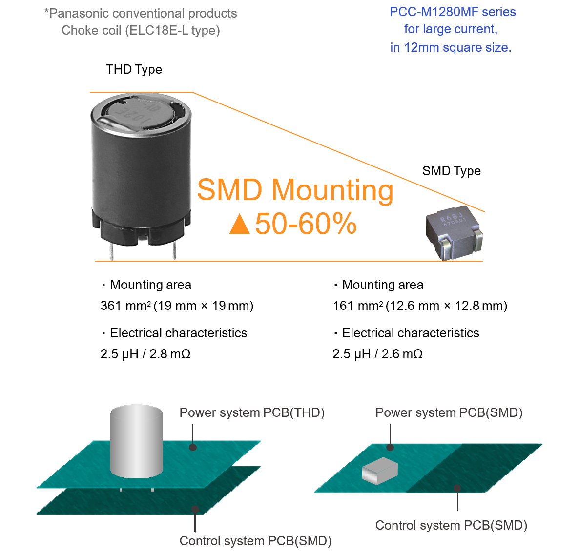
Industry’s smallest class of surface-mounted inductor capable of passing large currents
| Series | Size | Rated Current |
|---|---|---|
| PCC-M1280MF | 12.6×13.2×8.0 mm | 20.2∼53.5 A (*1) |
| PCC-M15A0MF | 17.2×15.6×10.5 mm | 30∼83 A (*2) |
(*1) DC current which causes temperature rise of 40K. Parts are soldered by reflow on multilayer PWB with high heat dissipation performance. Note: Heat radiation constant are approx. 20 K/W measured.
(*2) DC current which causes temperature rise of 40K. Parts are soldered by reflow on multilayer PWB with high heat dissipation performance. Note: Heat radiation constant are approx. 13.8 K/W measured.

The metal composite material using unique metal magnetic material and the wired coil using thick copper wire enable gapless monolithic structure by monolithic molding of the magnetic material and the wired coil without gap.
As a result, the coil heat generation is reduced and the coil heat dissipation is increased, and a large current of 20 to 87A is achieved while reducing the volume by half compared to the ferrite type.
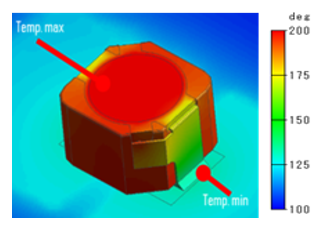
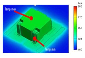
The monolithic structure by the metal magnetic material enables
more than twice of high heat dissipation
The inductor enables ECUs to be directly mounted on engines by achieving excellent heat and vibration resistance.
- Heat resistance : 160 °C / 2000 h in SMD type
- Vibration-resistance : 5 Hz to 2 kHz / 30 G
No abnormal condition in product and solder part as reliability test result
| Items | Condition | Evaluation time | |
|---|---|---|---|
| Thermal Shock | -40 °C to +160 °C | 2000 cyc. | |
| Vibration | 30 G(5 Hz to 2 kHz) | XYZ(2 h each) | |
| Heat Resistance | 160 °C | 2000 h | |
| High Temp. Life | 160 °C, DC rated current | ||
| Humidity Resistance | 85 °C,85% RH | 2000 h | |
| Humidity Life | 85 °C,85%RH, DC rated current | ||
| Cold Resistance | -40 °C | 2000 h | |
■Pretreatment condition: after 85±2°C,85%RH,168h, 3 times reflow aging
※Possible to set up vibration/reflow condition etc. according to customer's condition.
Vibration condition: 5 Hz to 2000 Hz/30 G/xyz / 2 hr. each
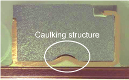
Heat resistance of 160°C is achieved by working on the composition of metal composite material. In addition, while the thick copper wire of the coil is drawn out to be used as terminals, an unique structure is adopted by fixing the terminals on the metal composite material body in a caulking structure on the bottom side, thus the vibration resistance is enhanced.
The environmental impact can be reduced through installation space saving.
By adopting a metal composite suitable for downsizing, the company achieved a smaller inductor size with a similar performance for ferrite type inductors, which makes it possible to reducing the installation area, reduce the size of equipment, and reduce the number of materials used. It is possible to reduce the environmental load.
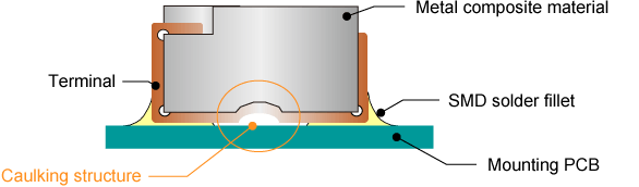
Unique terminal structure technology to assure heat capacity as SMD type, with the copper wire of the coil drawn out to be used as terminals
Application
Large capacity and down sizing requirements from function integration in accordance with increasing number of ECUs.
Application requires large capacity, down sizing, high reliability.
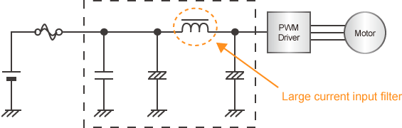
- ELECTRIC PUMP INPUT FILTER
- ELECTRIC FAN MOTOR INPUT FILTER
- DIRECT INJECTION INPUT FILTER
- BREAKING SYSTEM INPUT FILTER
- EGR INPUT FILTER
- ELECTRIC COMPRESSOR INPUT FILTER
- EPS INPUT FILTER
- BODY ELECTRIC SYSTEM INPUT FILTER
Circuit diagram
Line up
| Series | Parts no | Inductance*1 | DCR at 20 ℃ (mΩ) |
Rated current (A)Typ. |
Size [LxWxH] (mm) |
|||
|---|---|---|---|---|---|---|---|---|
| L0 (μH) |
Tolerance (%) |
Typ. (max.) |
Tolerance (%) |
△T= 40 K*2 ( ) *3 |
△L= –30 %*4 |
|||
| PCC-M1280MF | ETQP8MR33JFA | 0.33 | ± 20% | 0.7 (0.77) |
± 10% | 53.5 (44.4) |
84.5 | 13.2×12.6×8.0 |
| ETQP8MR68JFA | 0.68 | ± 20% | 1.1 (1.21) |
± 10% | 42.6 (35.4) |
56.9 | 13.2×12.6×8.0 | |
| ETQP8M1R0JFA | 1.0 | ± 20% | 1.36 (1.50) |
± 10% | 38.3 (31.8) |
44.4 | 13.2×12.6×8.0 | |
| ETQP8M1R5JFA | 1.5 | ± 20% | 1.8 (1.98) |
± 10% | 33.3 (27.7) |
29.9 | 13.2×12.6×8.0 | |
| ETQP8M2R5JFA | 2.5 | ± 20% | 2.6 (2.86) |
± 10% | 27.7 (23.0) |
32.1 | 13.2×12.6×8.0 | |
| ETQP8M3R3JFA | 3.3 | ± 20% | 3.6 (3.96) |
± 10% | 23.6 (19.6) |
27.6 | 13.1×12.6×8.0 | |
| ETQP8M4R7JFA | 4.7 | ± 20% | 4.9 (5.39) |
± 10% | 20.2 (16.8) |
24.7 | 13.1×12.6×8.0 | |
| PCC-M15A0MF | ETQPAMR33JFW | 0.33 | ± 20% | 0.42 (0.48) |
± 15% | 83 (69) |
103 | 17.2×15.6×10.5 |
| ETQPAMR68JFW | 0.68 | ± 20% | 0.70 (0.77) |
± 15% | 65 (53) |
71 | 17.2×15.6×10.5 | |
| ETQPAM1R0JFW | 1.0 | ± 20% | 0.88 (0.97) | ± 15% | 57 (47) |
52 | 17.2×15.6×10.5 | |
| ETQPAM1R5JFW | 1.5 | ± 20% | 1.10 (1.21) | ± 10% | 52 (43) |
43 | 17.2×15.6×10.5 | |
| ETQPAM2R5JFW | 2.5 | ± 20% | 1.70 (1.87) | ± 10% | 42 (34) |
41 | 17.2×15.6×10.5 | |
| ETQPAM3R3JFW | 3.3 | ± 20% | 2.40 (2.64) | ± 10% | 35 (29) |
37 | 17.2×15.6×10.5 | |
| ETQPAM4R7JFW | 4.7 | ± 20% | 3.10 (3.41) | ± 10% | 31 (26) |
30 | 17.2×15.6×10.5 | |
*1: Measured at 100 kHz
*2: The proved current value for making the overall temperature rise of 40K, when mounted on a multi-layer board with high-heat dissipation
*3: The proved current value for making the overall temperature rise of 40K, when mounted on a 4-layer circuit board of FR4 t=1.6 mm and DC current is applied.
*4: Saturation rated current : DC current which causes L(0) drop –30 %.