Is it essential to a data center?
The reasons why a 48-V power supply is required and the challenges of power supply design (1)
-Why is a 48-V power supply required?-
2021-07-27
Applications of 5G technology are accelerating daily, while processors including CPU, GPU, FPGA, ASIC, etc., used in data centers and edge AI servers, are evolving. With such evolution, problems such as load fluctuation and heat generation are created. As a solution, 48-V power feeding is getting more attention.
Accordingly, this article discusses problem solutions applied to data centers with 48-V power feeding.
Evolution of data centers for supporting 5G societies
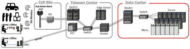
The next-generation high-speed communication 5G services have started recently. Over the next ten years until 2030, various convenient features not available in the past are expected to surround us with a substantial improvement in communication performance. Widespread use of mobile phone contracts with unlimited communication capacity, remote medical treatments and construction work by MR (mixed reality technology), and all the way down to general-purpose self-driving. As the infrastructure to support the availability of these services, technology evolution and deployment plans for 5G wireless base stations are updated almost daily. However, what we should not forget, at the same time, is the advancement of data centers for executing the arithmetic processing of applications in the background. (Fig. 1)
The high-performance processors such as CPUs, ASICs, etc., for executing calculations have improved their performance utilizing multi-core design and higher clock operation. In addition, performance improvement is tried through an efficient combination of different types of processors (Fig. 2)
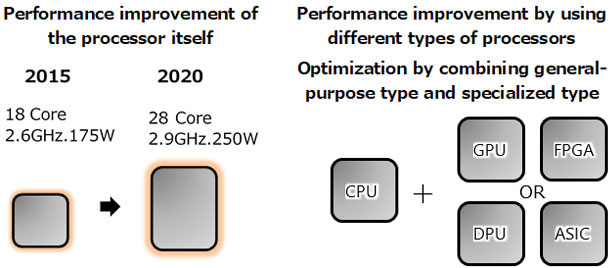
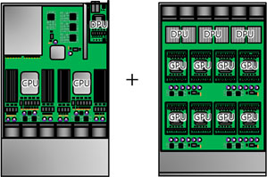
The high-performance processors used in the previous data centers were primarily CPUs used for servers along with ASICs used for communication processing in switches and routers, but now high-performance processors used for performance optimization (such as GPU and ASIC for AI processing, FPGA for enabling flexible processing, and DPU for efficient data processing, etc.) are more widely used. For example, leap-frog improvement of operational performance is achieved by applying large-scale processing of a server having two CPUs combined with 8 GPUs in a separate housing. (Fig. 3)
Power consumption issues of a data center
One of the problems deemed difficult in recent years in the evolution of data centers is the increasing power consumption.The main reason exists in processors. In the past, power consumption was suppressed by improving processing performance through adopting a finer cutting process. However, in recent years, the power reduction effect by adopting a finer process is said to be less due to physical restrictions. (Dull-out effect of Moor’s law)
Based on such background, power consumption of data centers has been increasing gradually, and without taking action now, global-scale power depletion may be produced. Therefore, the reduction of power loss by reducing wasted heat is becoming increasingly important.
The leading index widely used for power efficiency in data centers is PUE (Power Usage Effectiveness). PUE is expressed, as shown in the following formula; a smaller value indicates good power efficiency. The companies offering cloud services try to suppress the PUE of each data center by applying an individual technological approach (Fig. 4)
Quote source:https://sustainablejapan.jp/2017/08/06/pue/27735
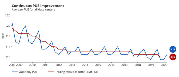
Quote source:https://www.google.com/about/datacenters/efficiency/
While each company actively reduces power consumption, Google LLC was the leader in adopting the 48-V DC power feeding method. This technique has gained widespread support toward optimization of components and circuits and achieving industry-wide adoption in the data-center-related businesses.
Current status of 48-V DC power feeding in the data centers
Advantage of 48-V DC power feeding
48-V DC power is applied to the AC/DC power source to the DC/DC power input terminal of each computation board. For example, in carrying 12-kW power, 12 V 1000 A is equivalent to 48 V 250 A, but from the viewpoint of power loss by distribution (distribution loss = I2R), a large difference is generated.
By assuming the resistance of the distribution path is 0.1 mΩ, distribution loss with 12 V is 100 W, but in the case of 48 V, the loss is 6.25 W, generating a 16 times difference. (Fig. 5)
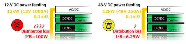
As shown in this example, when the power per rack exceeds 10 kW, the power distribution loss generated by traditional 12-V DC power is said to reach an intolerable level, but a 48-V DC power supply significantly contributes to power saving for a data center.
Selection of power supply sources
When a 48-V DC power feeding is adopted, the power configuration of the DC/DC converter needs to be changed from the 12-V DC power supply. Briefly described, two methods are used. The single-stage method reduces the 48-V power source to the load voltage by using a single power supply. The two-stage method reduces the source voltage to an intermediate voltage and then to the load voltage. (Fig. 6)
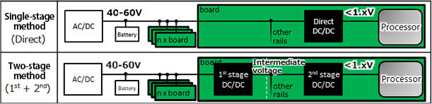
Each of single-stage method and two-stage method has advantages and disadvantages as shown below, and either method is selected according to the design requirements such as size, cost, etc. (Table 1)
| Method | Advantages | Disadvantages |
|---|---|---|
| Single-stage method | Power supply circuit size can be made smaller. | Usable circuits and components are limited. = High cost |
| Two-stage method | Large selection of circuits and components. = Low cost A compatible design with the existing 12-V server is possible. |
The power supply circuit size gets larger. |
Of the two methods shown, one that would take the mainstream is the two-stage method. The reason comes from compatibility with the existing 12-V servers and stable component supply in the introduction stage of the 48-V system. The simplest method of achieving compatibility is to attach a compact 48 V - 12 V conversion board after the existing 12-V server board. The two-stage design would substantially impact power source efficiency if the existing conditions are maintained, but the ideas shown below are in progress to maintain overall efficiency.
- ・Improvement of the power supply itself
- Adoption of non-stabilized output, resonance switching method, etc. (1st stage) and low input voltage (2nd stage) for efficiency improvement
- ・Adjustment of voltage and current path
- Optimization of distribution voltage and path length in each power source for reducing the total distribution loss
Importance of high-performance, high-quality bulk capacitors (*1)
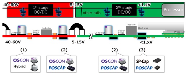
To achieve high reliability and stable operation of the two-stage power supply structure shown here, it is important to select the best-suited components for the 1st- and 2nd-stage DC/DC converters.
For each input and output part for the 1st and 2nd stages of the 48-V power supply, appropriate Panasonic capacitors are shown below. (Fig. 2, Table 2)
| Position | Bulk capacitor standard rating | Product | Designer’s voices |
|---|---|---|---|
| (1) 1st stage input (40-60V) |
47μF ~100μF |
Aluminum
Electrolytic Capacitors  |
Supporting low cost and large capacitor (Concern exists for temperature characteristics and capacity deterioration caused by liquid electrolyte). |
OS-CON
 |
Supporting temperature stability, long life, and reliability with total solid material (When reliability has priority, E-cap cannot be used). | ||
Hybrid
 |
Supporting the intermediate features between E-cap and OS-CON by using semi-solid material. | ||
| (2) 1st stage output / 2nd stage input (5-15V) |
100μF ~470μF |
OS-CON
 |
Large capacity and high ripple current characteristics are effective for large current fluctuation backup and power source smoothing. |
POSCAP
 |
A component height of 2 mm is effective for high-density servers requiring back-surface component mounting and large-current fluctuation backup for accelerator cards. | ||
| (3) 2nd stage output (<1.xV) |
220μF ~1000μF |
SP-Cap
 |
Large capacity and low ESR characteristics are effective for large current fluctuation backup. In addition, a component height of 2 mm is effective for enabling back-surface component mounting because the output board front surface is limited. |
POSCAP
 |
Compact and large capacity components are best-suited for high-density servers and accelerator cards. |
Panasonic’s conductive high-polymer capacitors are deemed effective as bulk capacitors (*1) important for power source stabilization.
The next session will focus on more detailed points to be considered when selecting capacitors in each position of input and output units of the 1st stage and 2nd stage DC/DC converters.
(*1) Bulk capacitors
Capacitors that have the largest capacitance in each position of a power circuit are used with smaller capacitance capacitors in parallel.
The role of these capacitors is to suppress voltage fluctuation by supplying or absorbing current at the time of current increase or reduction caused mainly by input or output.
Related product information
Tags related to this article
