Noise Management using Capacitors: Effectiveness of Conductive Polymer Electrolytic Capacitors
2018-01-22
Noise Management using Capacitors
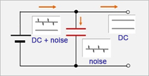
Noise management using capacitors makes use of their characteristics of high impedance in low-frequency ranges and low impedance in high-frequency ranges. A capacitor is connected between a power supply line and grounding to prevent noise propagation to the subsequent circuit (Load side) by passing the noise to the grounded side. This capacitor is sometimes referred to as a bypass capacitor because it bypasses noise to the ground, or as a decoupling capacitor because it separates the circuits of the previous and latter stages. This basic characteristic of capacitors can be used for noise management because most noise is from high-frequency AC.
In addition to the above, capacitors have the role of maintaining constant power supply voltages. When a steep load fluctuation occurs (Current flowing through a power supply line suddenly changes), the response of the power supply may not be able to follow up. In such cases, the fluctuation of the power supply voltage can be suppressed by sharing the load current using charge stored in capacitors.
Points to be taken into consideration for noise management using capacitors
There are some points to be taken into consideration for noise management using capacitors to achieve adequate effects.
① Select capacitors with low impedance in noise frequency ranges.
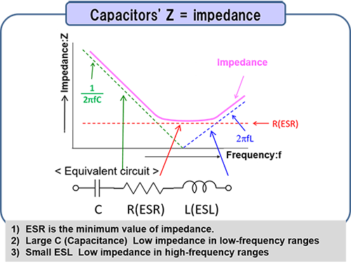
Ideal capacitors consist only of C (Capacitance components). However, actual capacitors include R (Resistance components) and L (Inductance components). As shown in the diagram on the right, they are indicated as ESR (equivalent series resistance) and ESL (equivalent series inductance) in equivalent circuits. The impedance of capacitors changes in accordance to frequencies; it decreases with increasing frequencies in low-frequency ranges.
The impedance becomes minimum near the self-resonant frequency (Frequency where (1/(2πfC) = 2πfL), and after this point, it increases with increasing frequencies. Therefore, it is important to select capacitors with low impedance in the frequency range of the target noise.
② Minimize the range in which noise current flows (Arrange a capacitor close to a load such as IC).
③ Minimize the inductance of the patterns on mounting boards (Minimize a distance between a pin and a capacitor on the IC).
These two points are often mentioned in board layout design. To minimize noise emission and intrusion, capacitors need to be placed as close to loads as possible for bypassing/decoupling. Line inductance, including capacitor leads, may generate spike noises and therefore need to be minimized (= Wiring (leads) need to be short).
Noise management of switching power supply output ripple
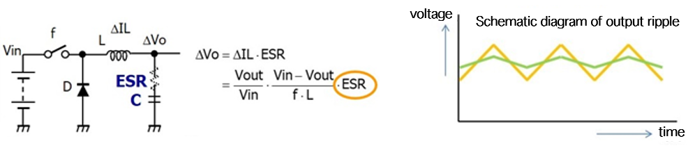
Ripple noise included in the output voltage of switching power supplies is an important noise to be suppressed in electronic circuits. Output ripple voltage ΔVo of a voltage step-down switching power supply is generated by the ripple component ⊿IL of current flowing through the inductor and the capacitance, ESR and ESL of the output capacitor. To suppress the output ripple voltage, it is effective to increase the capacitance, decrease ESR, etc., of the output capacitor. When aluminum electrolytic capacitors, etc. are used for output, the ripple voltage is determined by the ESR of the capacitors in some cases because of adequately large capacitance components. Therefore, when using capacitors with a relatively large capacitance such as aluminum electrolytic capacitors to minimize the output ripple voltage of switching power supplies, it is necessary to select output capacitors with low ESR. In addition, ESL, which is also an element constituting a ripple voltage in switching operation, also needs to be low.
Conductive polymer electrolytic capacitors
Panasonic offers a lineup of conductive polymer electrolytic capacitors (SP-Cap, POSCAP, OS-CON, hybrid capacitors) with excellent characteristics that are optimal for noise management,. We will introduce SP-Cap and POSCAP here.
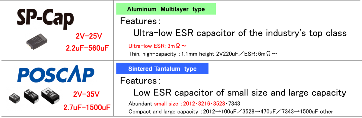
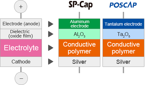
SP-Cap is a type of aluminum electrolytic capacitor with an aluminum anode and aluminum oxide dielectric. POSCAP, which has tantalum anodes and tantalum oxide dielectric , is one of the types of tantalum solid electrolytic capacitors. Both use conductive polymer (polypyrrole, polythiophene) for electrolyte. The conductivity of the conductive polymer is approx. 100 s/cm, which is 10,000 times higher than that of electrolyte liquid used in common aluminum electrolytic capacitors and 1,000 times higher than manganese dioxide used in tantalum electrolytic capacitors. The use of this conductive polymer has achieved a very low ESR. In particular, SP-Cap features an industry-leading ultra-low ESR, whereas POSCAP features small size and large capacity.
Electric characteristics of SP-Cap/POSCAP
Comparisons with electrolytic capacitors
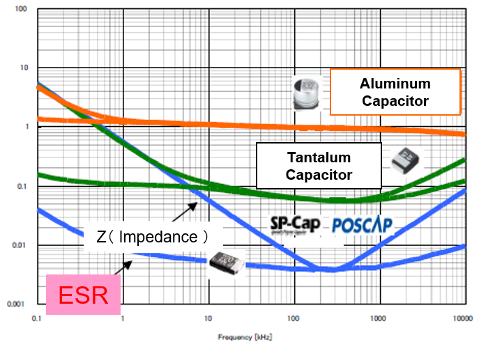
As described earlier, SP-Cap/POSCAP feature a very low ESR compared with common electrolytic capacitors (Aluminum electrolytic capacitors, tantalum electrolytic capacitors). The graph on the right compares the frequency characteristics of ESR and impedance of aluminum and tantalum electrolytic capacitors and SP-Cap/POSCAP with the same capacitance. Because SP-Cap/POSCAP features very low ESR, in particular, their impedance near the resonance point is significantly lower than that of other electrolytic capacitors.
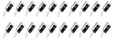
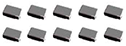
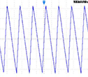
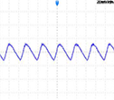
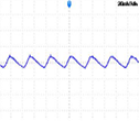
Therefore, a single SP-Cap/POSCAP can be expected to achieve the equivalent or higher ripple reduction effects as that of multiple aluminum or tantalum electrolytic capacitors. As an example, the following table compares the ripple reduction effects when 20 units of 330 uF aluminum electrolytic capacitors or 10 units of tantalum electrolytic capacitors are replaced by one unit of SP-Cap. As you can see, a single SP-Cap achieves adequate ripple reduction effects, which can significantly reduce quantity, space, and costs.
| Aluminum electrolytic capacitors Impedance: Typ.120mΩ (at 300kHz) |
Tantalum electrolytic capacitors Impedance: Typ.55mΩ (at 300kHz) |
SP-Cap Impedance: Typ.5mΩ (at 300kHz) |
||
|---|---|---|---|---|
| Quantity of capacitors |
input 300kHz 670mVp-p |
20pcs (6600µF) | 20pcs (6600µF) | 1pcs (330µF) |
 |
 |

|
||
| Ripple waveform |
 |
 |
 |
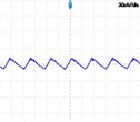 |
| Ripple voltage | 24mVp-p | 16mVp-p | 14mVp-p |
Comparisons with MLCC
Next we will make comparisons with MLCC (multilayer ceramic capacitors), which are often utilized for noise removal because of their low ESR and ESL. Although MLCC has excellent characteristics for noise removal, they also have specific characteristics that require consideration in design processes.
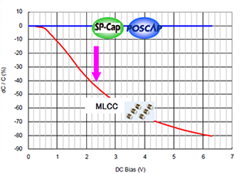
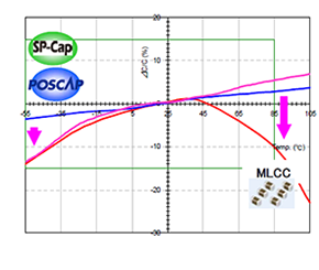
1. Stability of capacitance
It is known that capacitance decreases due to DC bias and temperature characteristics. Comparisons in terms of DC bias and temperature characteristics are shown below. With regard to the DC bias characteristic, in particular, capacitance may drop to approx. 80% of the rated capacity depending on the voltage in some cases. Capacitance may also significantly change by several tens of percent because of temperature changes. Comparing these characteristics to MLCC , the capacitance of SP-Cap/POSCAP changes little, showing very stable characteristics.
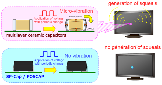
2. Squeals due to piezoelectric effects
MLCC uses materials with piezoelectric effects on dielectrics and therefore capacitors micro-vibrate when the applied voltage changes periodically, causing the mounting board to resonate and generate squeals, i.e., sound in the audible band. Dielectrics used in SP-Cap/POSCAP have no piezoelectric effects and accordingly do not generate squeals.
In fact, SP-Cap/POSCAP have been adopted in large numbers for notebook PCs and monitors as a measure against squeals by MLCC. In addition, it is also an effective measure to use SP-Cap/POSCAP when micro-vibrations generated by MLCC can affect equipment control or measurement results.
Safety
Solid electrolytic capacitors such as tantalum electrolytic capacitors are associated with concerns such as the capacitors short-circuiting and catching fire.
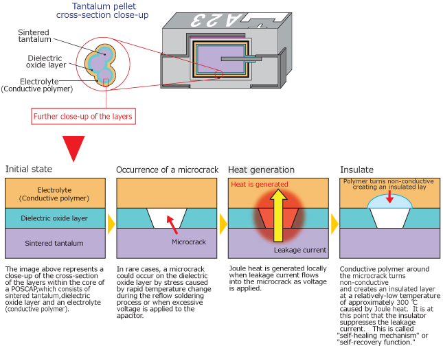
SP-Cap/POSCAP, which use a conductive polymer as dielectrics, achieves high reliability by suppressing failures. Electrolytic capacitors sometimes suffer damage to their dielectric oxide film due to external stress, etc. Common tantalum electrolytic capacitors can short-circuit and catch fire from this damaged section. When conductive polymer is used, leakage current also concentrates in the damaged section, causing local Joule heat. However, the conductive polymer materials at the damaged section become insulators with a relatively low heat of approx. 300ºC, suppressing current. SP-Cap/POSCAP can therefore be regarded as very safe capacitors in comparison to common tantalum electrolytic capacitors.
<POSCAP insulation recovery mechanism>
Related product information
Tags related to this article
This document summarizes the Noise measures related articles posted as technical information for the Optimal Solutions for Circuit Design.
