Basic Knowledge of Capacitors (1)
-Mechanism, Usage, Characteristics-
2018-05-28

Capacitors are one of the three major types of passive components, along with resistors and coils. Every electric/electronic circuit uses capacitors and cannot operate normally without them. This is also the case with cutting-edge equipment such as smartphones, IoT equipment, servers, networks, and wireless communication systems. Capacitors, whose performance affects the performance of various electronic equipment, are now key components.
Basic Structure of Capacitors
In short, capacitors are components capable of storing electricity and releasing the stored electricity when necessary. They store a smaller amount of electricity (charge) than batteries and therefore can supply current for only a short period of time by releasing their charge (discharge). However, capacitors can repeat the charging (storing a charge) and discharging cycle.
A schematic diagram of a capacitor is shown below. The capacitor consists of an insulator (dielectric) sandwiched between parallel metal plates (electrodes). Applying a DC voltage across the metal plates (electrodes) will store a charge, which illustrates the power storage principle of capacitors. The amount of charge that can be stored is referred to as capacitance, and capacitance ‘C’ is determined by permittivity ‘ε’ of the insulator, surface area ‘S’ of the electrodes, and thickness ‘d’ of the insulator.
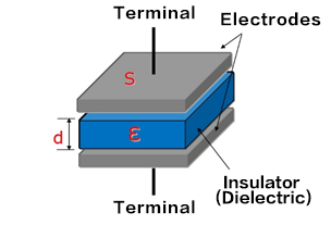
S
d
- C
- Capacitance
- ε
- Permittivity of the insulator
- S
- Electrode surface area
- d
- Thickness of the insulator
The capacitance C will increase when the permittivity ε of the insulator is increased, the surface area S of the electrodes is increased, or the thickness d of the insulator is decreased.
Voltage and Current of Capacitors
There is no direct flow of current through capacitors since their interior is insulated. However, because capacitors perform charging and discharging in accordance with variations in the applied voltage, it appears as if current flows through them. The magnitude of the current flowing through capacitors increases with an increase in the temporal change of the voltage, as indicated by the equation below.
- Ic
- : Capacitor current (A)
- C
- : Capacitance (F)
- dVc/dt
- : Line slope of V-t curve
(Example 1) Case of charge/discharge waveforms
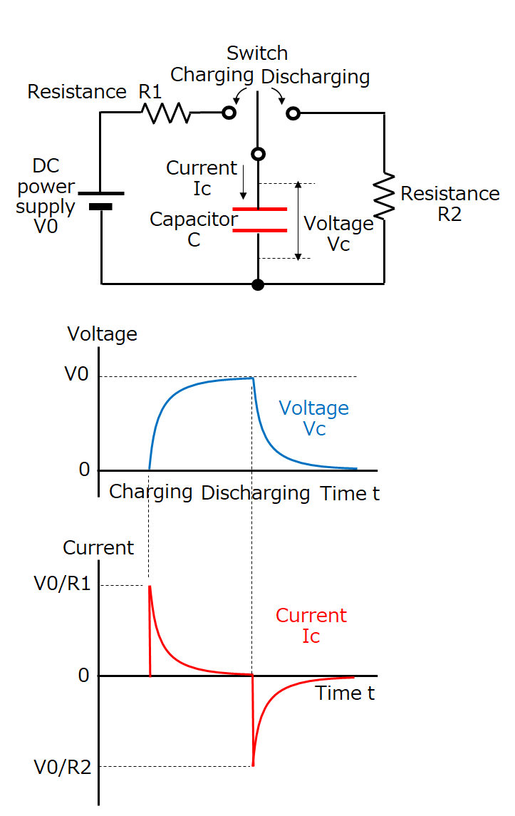
Explanations about the voltage and current of a capacitor are given when an uncharged capacitor is charged from a DC power supply via a resistance and then discharged.
In the circuit diagram, when the switch is turned ON to the charging side, a peak current of V0/R1 flows through the capacitor, after which the current decreases with an increase of the voltage Vc of the capacitor. When Vc = 0, charging is completed, and the current becomes zero.
Next, when the switch is turned ON to the discharging side, a peak current of V0/R2 flows through the capacitor, after which the current decreases with a decrease of the voltage Vc of the capacitor. When Vc = 0, discharging is completed, and the current becomes zero.
Here, we would like you to understand that the magnitude of the current Ic of the capacitor depends on the magnitude of the change of the voltage Vc of the capacitor.
Furthermore, when the switch is turned ON and a current of V0/R flows, if R = 0, then an infinite current can theoretically flow, completing the charge/discharge cycle instantaneously.
(Example 2) Case of AC waveforms
The voltage and current of a capacitor when an AC voltage is applied to it are explained.
Example 1 described that the magnitude of the current flowing through a capacitor follows the magnitude of the change of the capacitor's voltage. This is the same with AC waveforms.
- (1) First, a large current flows when the voltage rises from 0 V. However, the current decreases with a decrease in the rising speed of the voltage and becomes zero when the voltage reaches its maximum value (no voltage change).
- (2) A negative current starts flowing when the voltage starts falling from its maximum value; the current reaches its maximum value when the voltage becomes zero (maximum voltage change).
- Regions (3) and (4) can be understood in the same manner as above.
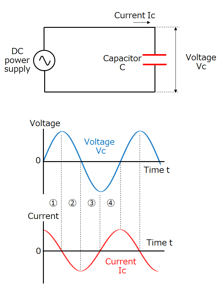
In addition, a larger current flows when the voltage change is larger, which means that a larger current flows at higher frequencies at which voltage changes are larger.
The equation below shows the current (effective value) that flows at this point.
- Ic
- : Capacitor current (Arms)
- π
- : pi (3.14)
- f
- : Frequency (Hz)
- C
- : Capacitance (F)
- Vc
- : Power supply voltage (Vrms)
Basic Use of Capacitors
As described earlier, capacitors possess and provide the following properties in electric circuits: (1) Capable of instantaneous charge and discharge; (2) Do not pass DC but pass AC; and (3) Pass AC more easily at higher frequencies.
Here are circuit examples showing typical uses of capacitors.
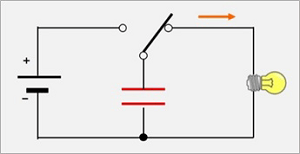
[Discharge circuits]
Discharge circuits operate loads connected to them by discharging the charges stored in capacitors. They are used in strobe lights for cameras, emergency backup power supplies, etc., since they can discharge large currents instantaneously. In the circuit example, connecting the switch to the power supply side will charge the capacitor, with the charging stopping when a charge reaching the power supply voltage is accumulated. Connecting the switch to the load (light bulb) side will start discharging the capacitor, thereby lighting the bulb.
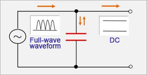
[Smoothing circuits]
Smoothing circuits convert AC to DC by smoothing the ripples of rectified AC. A typical example is a power supply circuit. The AC input voltage is rectified (full-wave rectification in the circuit example) by a diode bridge, and the resulting voltage waves (ripples) are smoothed by the capacitor.
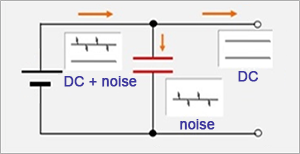
[Decoupling circuits]
Decoupling circuits, as their name suggests, separate coupled signals by using capacitors. In this example, by placing a capacitor in a signal path that includes high-frequency AC components (noise) in addition to the base AC, as shown in the diagram, only the high-frequency noise components pass through the capacitor and are separated, which prevents their propagation to the following stage. One example of such use is removing the switching noises of switching power supplies.
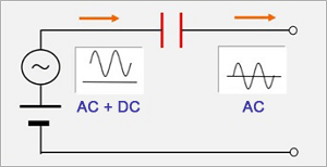
[Coupling circuits]
Coupling circuits pass only AC components, but not DC components.
They are used to eliminate the effect of DC components (also referred to as DC cut) in audio signal amplification circuits, etc.
Characteristics of Capacitors
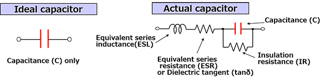
Ideal capacitors consist only of capacitance components. However, actual capacitors include resistance and inductance components. These parasitic components significantly affect the performance of capacitors. The diagram below shows the simplified equivalent circuits of capacitors.
As shown in the diagram, an equivalent circuit of an actual capacitor includes ESR (equivalent series resistance) and ESL (equivalent series inductance). In addition, there should ideally be insulation between the electrodes of a capacitor. However, in reality, some leakage current exists.
These components are summarized below.
| Characteristic Items | Explanations |
|---|---|
| Capacitance(C) |
|
| Equivalent series resistance (ESR) dielectric tangent (tanδ) |
|
| Insulation resistance (IR) |
|
| Equivalent series inductance (ESL) |
|
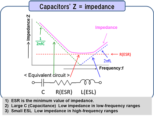
Another important characteristic is impedance. In short, impedance is the voltage to current ratio in AC circuits and equivalent to the resistance in DC circuits. Its symbol is Z, and is expressed using Ω, as with resistance.
The impedance (Z) of capacitors is expressed by equation (1), and the absolute value of impedance is calculated by equation (2) below.
② |Z| =
- Z
- : Impedance [Ω]
- R
- : Resistance components=ESR [Ω]
- j
- : Imaginary number
- π
- : pi (3.14)
- f
- : Frequency [Hz]
- L
- : Inductance component=ESL [H]
- C
- : Capacitance [F]
These equations indicate the following.
- 1) The impedance is determined mostly by capacitance (C) in low-frequency ranges.
- 2) The impedance is determined by ESR at self-resonant frequencies (frequencies with 2πf L = 1/(2πf C).
- 3) The impedance is determined mostly by ESL in high-frequency ranges.
- 1) Noise frequencies and the self-resonant frequency of the capacitor are close.
- 2) Small ESR
- 3) Small ESL in the case of high-frequency noises
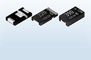
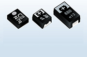
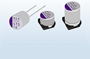
Types of Capacitors
There are a variety of capacitors depending on the materials used, structures, etc. Capacitors' features differ depending on their type, and capacitors are selected in design phases based on these features. The diagram below shows major types of capacitors.
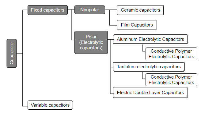
The features of each type of capacitor will be explained in detail in the next issue.
Related product information
Tags related to this article

This document summarizes the Basic Knowledge of Capacitors posted as technical information for the Optimal Solutions for Circuit Design.