Resistor Color Codes: Thorough Explanations of How to Interpret, Calculate, and Remember Them!
2025-10-24
Panasonic Industry boasts a history of over 90 years in resistor manufacturing. In 1933, based on Konosuke Matsushita's philosophy that "good products are made from good parts," the company began producing carbon film resistors for radio receivers. Since then, the company has shipped a cumulative total of more than 2 trillion resistors, supporting the development of electronic devices worldwide.
Today, surface-mount resistors (SMD) have become mainstream, and the production of color-coded resistors has been discontinued. However, resistor color codes still play an important role as fundamental electronics knowledge, both in educational settings and among engineers.
This article provides detailed explanations of resistor color codes, including how to interpret them, their meaning, their relationship with the international standard (IEC 60062), and their application in product design.
1. What are Color Codes? Why are Resistors Color-Coded?
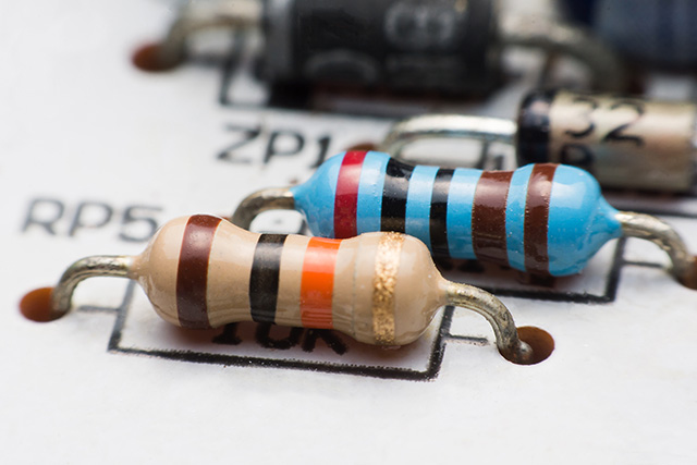
Resistors are essential for designing and repairing electronic circuits. The colored bands (color codes) on their surfaces provide important information indicating their resistance values and tolerance.
Resistor color codes are based on an international standard for visually representing resistance values, in accordance with the IEC 60062 standard. Since small resistors, in particular, have limited space for printing numerical values, colored bands are used to indicate their resistance.
From left to right on the resistor diagrams below, these color bands represent significant figures, multipliers, errors, temperature coefficients, and other information.
2. How to Interpret Color Codes
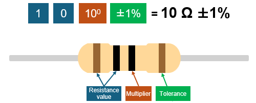
Resistor color codes are primarily divided into three types: four-band, five-band, and six-band. The following explains how to interpret each type using a color-to-value correspondence table.
- 1st and 2nd bands: Resistance values
- 3rd band: Multiplier (Powers of 10)
- 4th band: Tolerance (±%)
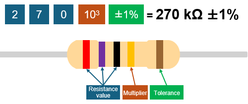
- First 3 bands: Resistance values
- 4th band: Multiplier
- 5th band: Tolerance
This color coding is frequently used for high-precision resistors, suitable for industrial applications.
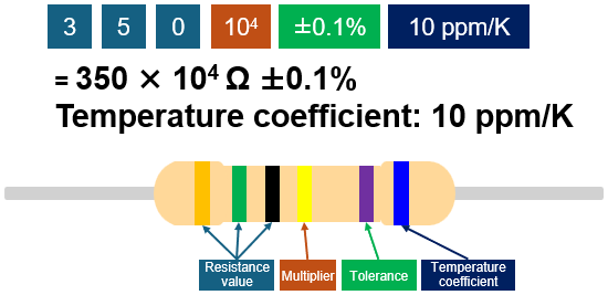
- First 3 bands: Resistance values
- 4th band: Multiplier
- 5th band: Tolerance
- 6th band: Temperature coefficient (ppm/K)
In addition to the information on the five bands, this band indicates the change in resistance due to temperature variations. The smaller the temperature coefficient of a resistor, the more resistant it is to temperature changes, making it suitable for precision measuring instruments and sensor circuits.
The term "ppm" stands for parts per million. For example, 100 ppm/K means that a 100°C change in temperature will result in a 1% change in resistance.
| Color | Digit | Multiplier | Tolerance | T.C.R |
|---|---|---|---|---|
| Black | 0 | ×100 | - | 250ppm/K |
| Brown | 1 | ×101 | ±1% | 100ppm/K |
| Red | 2 | ×102 | ±2% | 50ppm/K |
| Orange | 3 | ×103 | - | 15ppm/K |
| Yellow | 4 | ×104 | - | 25ppm/K |
| Green | 5 | ×105 | ±0.5% | 20ppm/K |
| Blue | 6 | ×106 | ±0.25% | 10ppm/K |
| Violet | 7 | ×107 | ±0.1% | 5ppm/K |
| Gray | 8 | ×108 | ±0.05% | 1ppm/K |
| White | 9 | ×109 | - | - |
| Gold | - | ×10-1 | ±5% | - |
| Silver | - | ×10-2 | ±10% | - |
| None | - | - | ±20% | - |
3. How to Identify Resistor Orientation
When there is a gold or silver band
A gold or silver band indicates tolerance and is marked as the last band. Accordingly, the correct orientation is to position the gold or silver band on the right and read the bands from left to right.
When there is no gold or silver band (high-precision resistors, etc.)
In general, of the two outermost bands marked on a resistor, the one with the wider spacing from the adjacent band is specified as the right-hand end. Another way to correctly orient a resistor is to position the band closest to either edge of the resistor body on the left-hand side.
4. Understanding Color Codes and Selecting the Most Suitable Resistor
Resistor color codes are the foundation of electronic circuit design. Interpreting them correctly ensures the safety and performance of circuits.
The company offers a lineup of highly reliable, high-performance chip resistors.
If you are considering replacing leaded resistors with chip resistors for mass production or miniaturization, please contact Panasonic.
5. Related product information
6. Related information
7. Tags Related to This Article

