2023-05-31
Application
Technical information
What is a Domain Control Unit (DCU) used in autonomous driving technology?
- Group of devices that contribute to higher performance -
A DCU (Domain Control Unit) is a type of ECU (Electronic Control Unit) that comprehensively processes data and makes decisions in an in-vehicle system and commands the operation of the vehicle. The number of DCUs is expected to increase year by year due to advances in driving assistance and autonomous driving technologies. This article explains the functions and system configurations of DCUs for ADAS and AD, and also introduces the lineup of electronic components that make up DCUs.
Difference between ADAS and AD
ADAS stands for advanced driver-assistance systems. The systems aim to improve driving safety by assisting drivers with driving. On the other hand, AD refers to autonomous driving, in which the AD system takes the initiative and drives automatically instead of humans.
Autonomous driving is defined by the SAE (Society of Automotive Engineers in the US) as level 0 to 5. From level 0 to 2, driving relies on human drivers, while levels 3 and above allow the driving to be controlled by the vehicle.
| Level | Name | Driven by | Driving area | Remarks |
|---|---|---|---|---|
| 0 | No driving automation | Human driver | - | The human performs all driving tasks |
| 1 | Driving assistance | Human driver | Limited | Provides driving assistance in part through tasks such as monitoring the vehicle's perimeter |
| 2 | Partial driving automation | Human driver | Limited | "Hands off" - Automates driving under specific conditions |
| 3 | Conditional driving automation | Vehicle | Limited | "Eyes off" - Automates driving under specific conditions |
| 4 | Advanced driving automation | Vehicle | Limited | "Brain off" - Automates driving under specific conditions |
| 5 | Full driving automation | Vehicle | No limitations | The vehicle performs all driving tasks under all conditions |
System configurations of ADAS and AD
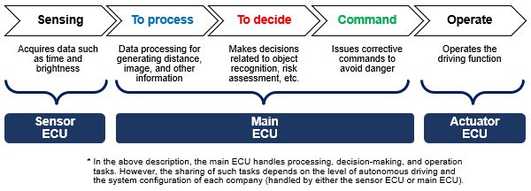
A sensor ECU, main ECU, and actuator ECU are required to implement ADAS and AD.
- Sensor ECU:Senses the surrounding environment, etc. (camera, RADAR, LiDAR, ultrasonic sensor, etc.)
- Main ECU:Data processing, decision-making, etc. (ADAS-ECU, AD-ECU, DCU, etc.)
- Actuator ECU:Performs and assists the driving operation (accelerator, brake, steering, motor, engine, etc.)
The system flow from sensing to operation is shown in Figure 1 below.
Domain and zone types
System configurations for ADAS and AD include a domain type (distributed) and zone type (consolidated).
- Domain type: Each function is classified into a group referred to as a domain, and ECUs are consolidated in each domain. Each domain is connected to other domains via the Gateway, and data processing is carried out in each domain ECU.
- Zone type: ECUs are consolidated at each key locations in the vehicle body. In addition, a central computer is installed in the center of the system, where data collected from the key locations is processed and handled.
| Configuration | Connection | Network |
|---|---|---|
| Domain type |
Consolidates domain-specific ECUs for each category (domain) All domains are connected via the Gateway Data processing is performed in each domain-specific ECU |
Common network standards are used for communication between sensors and domains Common network standards are used for communication between the domains and Gateway |
| Zone type |
Consolidates ECUs of different categories in each zone such as the front and rear of the vehicle Consolidates data from each zone to the Central Computer Integrates and concentrates data processing in the Central Computer |
There is a mixture of different network standards for communication between sensors and zones Common network standards are used for communication between the zones and Central Computer |
What is a DCU for ADAS and AD?
Each functional domain has a separate DCU (Domain Control Unit) (e.g. ADAS/AD, communication, powertrain, body, cockpit). Each DCU is responsible for consolidating a large number of devices that are in the same domain, processing data and making decisions in an integrated manner, and operating vehicles and devices through data transmission/reception and coordination with other DCUs.
For example, various sensor devices are integrated in DCUs for ADAS and AD, and sensed data are comprehensively processed and assessed, thereby implementing safe driving assistance and autonomous driving operations.
DCU market and equipment trends
The number of vehicles equipped with DCUs for domain type systems is expected to increase, mainly for autonomous driving levels 2 and below. As the level of autonomous driving increases further, the number of sensors installed must be increased accordingly to acquire data on the surrounding environment. As the number of sensors increases, the amount of data processed by DCUs increases, and the power consumption of the main semiconductor device that performs data processing increases with higher performance.
It is believed that devices for DCUs require "high current," "low loss," "miniaturization," "high frequency operation," and "high precision (voltage)."
DCU system configuration
Overview
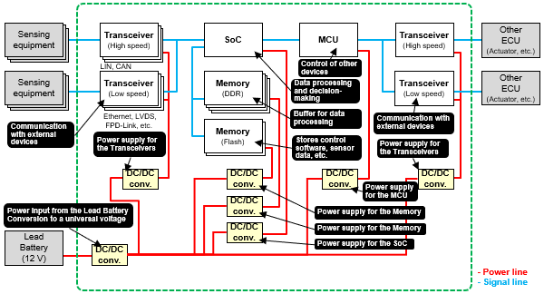
The DCU and its peripherals are connected as shown in Figure 3 below. The inside of the DCU is made up of transceiver circuits that communicate with sensor ECUs or other DCUs, an SoC (System on a Chip) that processes data from sensor ECUs and makes decisions, various memories, an MCU that controls driving based on the information assessed by the SoC, and DC/DC converter power supply circuits required to operate these various circuits.
Transceiver I/F
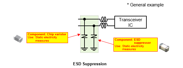
As shown in Figure 4, a transceiver circuit uses two lines to communicate with external devices (CAN, Ethernet, etc.). During communication, when noise or static electricity enters from the communication lines, this may lead to a failure of the transceiver IC. Therefore, it is common to configure a transceiver circuit with a chip varistor and an ESD suppressor to prevent static electricity.
Static electricity measures: Chip varistor, ESD suppressor
POINT- ❶ Contributes to the suppression of electrostatic (ESD) noise while maintaining circuit communication quality with a lineup of products having a wide range of capacitance characteristics.
- ❷ Chip varistors support low to high communication speeds with capacitance characteristics ranging from 8 to 250 pF.
- ❸ ESD suppressors support high-speed communication speeds with their capacitance characteristics of 0.1 pF.
DC/DC converter
(1) What is a DC/DC converter?
A DC/DC converter refers to a circuit that converts a DC voltage into a different DC voltage. Since the required voltage values differ for each circuit in DCUs, conversion to the appropriate voltage is necessary. It is common to configure a DC/DC converter circuit with FETs, coils, and capacitors.
(2) Circuit configuration by load type
The circuit configurations of DC/DC converters differ depending on the power, voltage, current, and load transient response to be handled. As shown in Figure 5, there are three main types of circuit configurations.
<TYPE A>
Due to the very large current values, multiple coils and FETs are used to share the load current (multiphase). In addition, since the voltage drops when sudden current fluctuations occur instantaneously, polymer capacitors are used in addition to MLCCs (ceramic capacitors) to prevent voltage drops.
<TYPE B>
Capacitors with a large capacity are used in circuits with a large current flow. Similarly to Type A, polymer capacitors are used in addition to MLCCs (ceramic capacitors).
<TYPE C>
This is a general DC/DC converter circuit.
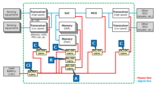
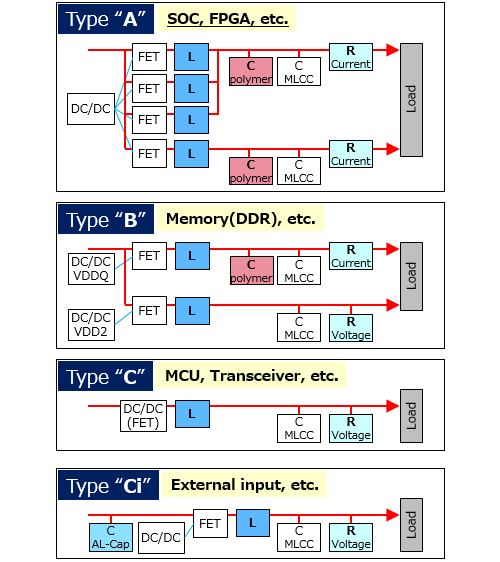
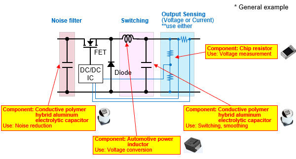
It is common for DC/DC converter circuits to use conductive polymer hybrid aluminum electrolytic capacitors for noise reduction at the input and smoothing at the output, automotive power inductors for voltage conversion, and chip resistors (high-precision chip resistors) for voltage measurements.
Noise reduction, switching, and smoothing ―― Conductive polymer hybrid aluminum electrolytic capacitor
POINT- ❶ Its high capacitance, low ESR, and high ripple performance contribute to circuit miniaturization and higher power features (low voltage and high current).
- ❷ Improved capacitance characteristics at high frequencies contribute to the elimination of noise, including high frequency components generated by high frequency switching of circuits over a wide band of frequencies.
Voltage conversion ―― Automotive power inductor
POINT- ❶ Contributes to circuit miniaturization and higher power features (low voltage and high current) due to the low loss and high current performance of metallic magnetic materials.
- ❷ Improved loss characteristics (low ACR) at higher frequencies contribute to the suppression of losses in high frequency switching circuits.
Voltage measurement ―― Chip resistor (high-precision chip resistor)
POINT- ❶ Contributes to the high-precision control of circuit output characteristics through the low resistance tolerance and low TCR performance with a thin-film structure.
Summary
The number of DCUs that are essential for the realization of autonomous driving is expected to increase in the future. This is because the higher the level of autonomous driving, the more sensors must be installed to acquire data on the surrounding environment. In the future, DCUs will be required to provide features such as "high current," "low loss," "high frequency operation," and "miniaturization" while reducing the power consumption of semiconductor devices. Aiming for DCU applications, Panasonic Industry offers a wide product lineup of highly functional devices that meet various requirements (Table 2).
| Components | Features | Large current | Low loss | High frequency | Miniaturization |
|---|---|---|---|---|---|
Conductive polymer hybrid aluminum electrolytic capacitors |
Low ESR High-reliability |
✔ | ✔ | ✔ | ✔ |
Automotive power inductor  |
High current, low loss High-reliability |
✔ | ✔ | ✔ | ✔ |
| Chip resistors (high-precision chip resistors)  |
High-precision, high heat resistance | ✔ | |||
Chip varistors |
Miniaturization and weight reduction | ✔ | |||
ESD suppressors |
Low capacitance Ultra high-speed data I/F |
✔ | ✔ |
Related product information
Related information